DMC50264N pinout

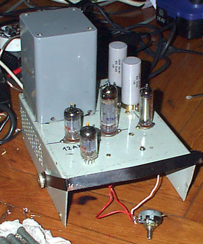
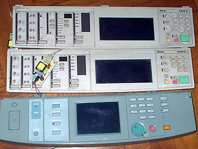
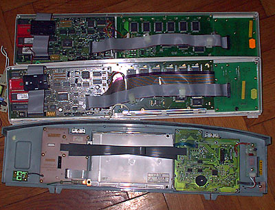
I removed few Optrex DMC50264N LCD modules with few buttons from some old laser printers. These modules are controlled by Mitsubishi M50530-026FP and M50521FP chipset. It is 4 lines 16 symbol special LCD module controlled by master CPU only by three wires. It is very simple serial to parallel converter made with the help of 74HC164A chip. All buttons are controlled in similar way using 74HC166A.

Pin out of J1 connector: 1- EXE, 2- +5V, 3- FPD, 4- GND, 5- CLCK, 6- GND, 7- FPS, 8- +24V.
For LCD control are used: GND, +5V, +24V (LCD contrast, can vary from 10…24V), CLCK, FPD, EXE.

Power lines are self explanatory. FPD is data stored in serial shift register and clocked by CLCK. EXE is connected to LCD controller and is used to strobe command from shift register. LCD controller can be controlled using 8+3 bits or 4+3 bits. This controller is connected in 4+3 way, so, programmer must send in the first SF command, that he will use 4 bit interface.

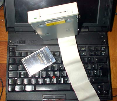
Data is shifted from MSB to LSB. Bits are in such order: (MSB) nc nc oc1 oc2 d7 d6 d5 d4 (LSB). For reverse engineering I wrote small program in MS Visual Basic and connected LCD module to LPT port using some TTL buffers (LCD module drains quite big load from data lines. Also, it drains quite high current from power supply- I used small ROHM BP5311 5V->24V DC/DC converter from same 5V power line).

Savel software for reverse engineering
The software is quite simple. The data is stored in windows in binary way. Selected rows are sent in serial way. Connections: LPT D3(pin 5)=DATA-FPD, D4(pin 6)=CLCK, D2(pin 4)=EXE

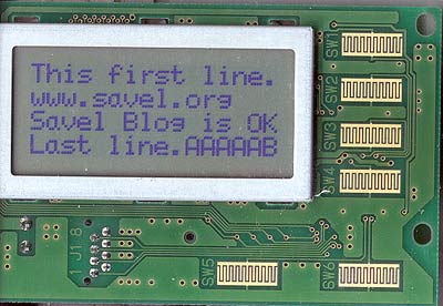
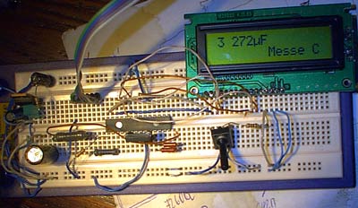
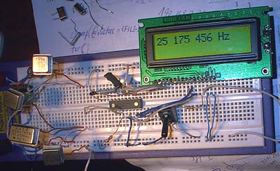
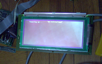
And here is the result:

DMC50264N Optrex

Data from the buttons are read in same way. One, untested, note- I didn’t noticed any RESET circuit. So user must count any bit.

Most important is the firs byte sent to LCD controller. I decided, that it must be &H0D0B, (&HDB). It is SF command: I/O=4bit, Font=8, Duty=10, RAM=11 (4 lines x 40 words). As only first 16 symbols are visible, programmer must add 24 dummy symbols.

Posted in Anything | 2 Comments

Schematics of my first tube amp

In older post I wrote that long time ago I built my first tube amp. Today, in old magazine, I found the schematics. As I remember, the output stage was working, but I made some mistakes in pre-amp. I left amp for very long time and my mother decided that it was junk and threw it away. 🙂

Tube Amp schematics
Big schematics for printing.

Recommendations for sound quality improvement: remove C9, C10 and C11. Change R2 to 240K, add feedback from output via 10K (R16) to Л1б cathode (dashed line in the circuit diagram).

Output transformer: Ш form core. Size of the core is about 4cm². Primary 2500 turns ПЭЛ 0.16 mm wire, secondary- 75 turns of ПЭЛ 0.8-0.9 mm wire. Output power ~3W, output resistance 4.5-5 Ω.

Tubes: Л1 – 6Н2П, 12AX7; Л2- 6П1П (miniature analog of 6П6С = 6V6!, maybe 6AQ5?)

Schematics from Радио 8, 1967.

Posted in Anything | Leave a comment

Waveform generator

For my audio amps I needed some small generator just for testing. And I also had MAX038 chip sample. Here is the abstract from datasheet:

The MAX038 is a high-frequency, precision function generator producing accurate, high-frequency triangle, sawtooth, sine, square, and pulse waveforms with a minimum of external components. The output frequency can be controlled over a frequency range of 0.1Hz to 20MHz by an internal 2.5V bandgap voltage reference and an external resistor and capacitor. The duty cycle can be varied over a wide range by applying a ±2.3V control signal, facilitating pulse-width modulation and the generation of sawtooth waveforms.
osc
Frequency modulation and frequency sweeping are achieved in the same way. The duty cycle and frequency controls are independent.
Sine, square, or triangle waveforms can be selected at the output by setting the appropriate code at two TTL-compatible select pins. The output signal for all waveforms is a 2VP-P signal that is symmetrical around ground. The low-impedance output can drive up to ±20mA.

Signal generator circuit diagram
Schematics for printing.

Component placement:
Signal generator PCB

Component values are described in MAX datasheet.

PCB image for printing in PDF format.

Posted in Anything | 2 Comments

DIY Capacitance Meter

In German (sprut.de) pages I found small schematics for caps meter. This schematic is designed for electrolytic capacitor metering. According to author, device range is from ~10µF to ~65 500 µF. This is not very accurate meter, but it is suitable for testing big electrolytic capacitors used in computer mainboard. And you must remember, that all electrolytic caps capacitance is printed on the body of cap with tolerance of 10, 20%. And for very big one even up to -20% … +50%.!!!

I made it on my testing breadboard for testing. The rainbow wire going outside board is ICSP connector to Willem programmer.

Capacitance meter

The circuit is very simple. The MCU is Microchip PIC16LF876A-I/SP (I used this) or PIC16F876A.

Circuit diagram
Big schematics for printing.

ICSP connector must be connected to: DATA-RB7(pin 28), CLCK-RB6(pin 27), Vpp-MCLR(pin 1), Vcc-Vdd(pin 20), GND-GND(pins 8&19).

Warning! Capacitor must be discharged before connecting it to meter.

Posted in Anything | 2 Comments

16F84 Frequency counter

In elektronika.lt and in original pages at sprut.de there is placed simple frequency counter schematics. It consists only from Microchip PIC 16F84 cpu and LCD text module. Author states that this counter is capable metering frequencies from 400Hz to 50MHz. I used faster, 20MHz version of 16F84A-20I/P, and it managed to count 80MHz oscillator output.

Frequency counter on PIC MCU

It is made on testing breadboard and uncalibrated. I made it just for testing. And the schematics is almost unmodified.

frequency counter schematics
Circuit diagram for printing.

I used small TTL oscilators for testing. These devices are much more precise that cheap quartz crystal used in schematics. It is possible to adjust 10MHz and so you can calibrate your counter. Here is my testing readings- the device is uncalibrated.

Quartz Freq readings
12.000000 MHz 12000112 Hz
25.175000 MHz 25175456 Hz
28.322000 MHz 28322656 Hz
80.000 MHz 79999616 Hz

Posted in Anything | 10 Comments

Booting router from PCMCIA

At my workplace there is old big copying machine- Minolta Dialta. Recently we bought second hand printer module for it. It is called Minolta Pi 1800, GDI printer module. I decided to make it work in intranet.

It was possible to buy small hardware print server for this purpose, but I decided to do it in hard way. I have very old IBM thinkpad notebook without any hdd and fd.
Router-print-server

But this notebook has option to boot from PCMCIA card. This was interesting. Many years ago, in eBay, I bought small Casio PCMCIA flash cards. It is ATA Flash cards, only 1.8Mb size. They were preformatted as hard disks. So I enabled boot from PCMCIA and nothing interesting happened. I received some mystical IBM POST code. I deciphered it as “no boot device”. How to make boot device for PCMCIA card? I was lucky, as I have IDE to PCMCIA adapter. So I formatted cards and installed Win boot block… No boot at all.
Router-print-server
After lots of investigations and testing card on other computers I found, that PCMCIA card “disk” partition is not active. WindowsXP decided, that such devices are not suitable to be active and refused to mark them. Windows 98 was more crazy- when I started fdisk, it informed that fdisk can make active partitions only on primary ide channel… What a fucked programmer done this program?
In internet I found another program- mbrwizard, which let me mark card as active disk. Now I can boot Win98 from flash card. Next step is to squeeze freesco software to small card. It is option to install freesco to hard disk, but whole install is few bytes larger than my card. After consultation with Unix gurus from newsgroup, I downloaded latest version of dd (rawwrite) program for windows xp. It was quite hard to construct such curse:

dd if=image of=\\.\Volume{da77677e-928b-11da-99eb-806d6172696f}
🙂

And, at last, I booted freesco linux kernel…
Router-print-server

One of the last problems was to find device for root file system. But while examining kernel boot messages, I found that card is /dev/hdc

The problem was solved:
Router-print-server

Now I needed to configure all the stuff for print server and network. And now everything is working.

Posted in Anything | Leave a comment

Gallium

One day I had small attack of shopping and I bought small pellet of gallium. It is quite strange, non toxic metal. It’s melting point is only 30°C. To be exact- 29.7646°C. And boiling point is very high- 2204°C! It can melt in your hand. The only problem, it will stain your skin.

Gallium is widely used as gallium arsenide in light emitting diodes (LED) and solid state lasers.

Gallium pellet

While I was writing this post, my gallium pellet melted and stained plastic sack.

Now I need to find any use for it. Maybe it can be used to make “super-turbo” high quality audio jacks? No shaking connections, no oxide contacts…

Posted in Anything | 1 Comment

Second Amp schematics

Older post tube amp schematics looks something like this:

Tube amp circuit diagram
Big circuit diagram for printing

This schematics and tube amplifier is not designed for tube maniacs. It is designed to test tubes. Resistor’s and capacitor’s values may differ, because I build the amp and only later draw diagram.

V1- 12AX7 (can use 12AU7 or something, when input sygnal is strong), V2- 6П14П, V3- VR150 (150V zener), R12-200K, C2-0.1μF

Posted in Anything | Leave a comment

My second tube amp

I have lots of 12AX7 and 12AU7 pull-outs. And I need to test them. While building some testing gear, I decided to add one more tube and transform it to tube amplifier. Why it is “second tube amp”? Because, about 20 years ago I already almost build my first tube amp.

This is photo of tube amp:

Tube Amp
There are three tubes in amp. That fourth tube is just placed. Tubes are: 12AX7 (inserted 12AU7 too- it is working, but more quietly), 6П14П-ЕВ (6BQ5, 7189A) and VR150. VR150 is 150V “zener”, it is stabilising voltage for preamp.

Here you can see super-duper high-end guts of amp:

Tube Amp
Everything done from scrap components. I used my beloved japan electronics from 1966. Only output transformer is used from some old Soviet TV

Here tubes glow in the dark:

Tube Amp
My photo camera didn’t catch focus in the dark.

Posted in Anything | Leave a comment

Graphics LCD modules

Removed consoles from “big” copy machines. Two from Xerox 5343C and one from some other…

There are nice graphics LCD modules with backlight and touchscreen:

LCD module
As this module is removed with some processor board, when powered it tries to do something…

LCD modules
“Good side”

LCD modules
“Bad side”

It is OPTREX DMF50073N-F-FW with 15 control and power lines.

The touchscreen in these two modules are very simple- simple matrix of switches: 9×12.

The newer LCD module is more complicated. Ant touch screen is more precise- it is analogue, only 4 wires to screen. LCD module is EDMMR63WOF. With 12 wires for power and control. According to internet it is Panasonic 320×240 STN-LCD.

Posted in Anything | 7 Comments