I removed few Optrex DMC50264N LCD modules with few buttons from some old laser printers. These modules are controlled by Mitsubishi M50530-026FP and M50521FP chipset. It is 4 lines 16 symbol special LCD module controlled by master CPU only by three wires. It is very simple serial to parallel converter made with the help of 74HC164A chip. All buttons are controlled in similar way using 74HC166A.
Pin out of J1 connector: 1- EXE, 2- +5V, 3- FPD, 4- GND, 5- CLCK, 6- GND, 7- FPS, 8- +24V.
For LCD control are used: GND, +5V, +24V (LCD contrast, can vary from 10…24V), CLCK, FPD, EXE.
Power lines are self explanatory. FPD is data stored in serial shift register and clocked by CLCK. EXE is connected to LCD controller and is used to strobe command from shift register. LCD controller can be controlled using 8+3 bits or 4+3 bits. This controller is connected in 4+3 way, so, programmer must send in the first SF command, that he will use 4 bit interface.
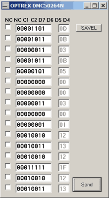
Data is shifted from MSB to LSB. Bits are in such order: (MSB) nc nc oc1 oc2 d7 d6 d5 d4 (LSB). For reverse engineering I wrote small program in MS Visual Basic and connected LCD module to LPT port using some TTL buffers (LCD module drains quite big load from data lines. Also, it drains quite high current from power supply- I used small ROHM BP5311 5V->24V DC/DC converter from same 5V power line).

The software is quite simple. The data is stored in windows in binary way. Selected rows are sent in serial way. Connections: LPT D3(pin 5)=DATA-FPD, D4(pin 6)=CLCK, D2(pin 4)=EXE
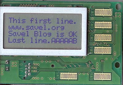
And here is the result:

Data from the buttons are read in same way. One, untested, note- I didn’t noticed any RESET circuit. So user must count any bit.
Most important is the firs byte sent to LCD controller. I decided, that it must be &H0D0B, (&HDB). It is SF command: I/O=4bit, Font=8, Duty=10, RAM=11 (4 lines x 40 words). As only first 16 symbols are visible, programmer must add 24 dummy symbols.

Hi
I have the same DMC50264N LCD and I would like to control my lcd with a microcontroler MHC908GP32 . I would like to know where i can find the BP5311 or an equivalent and if I can make 24V with some Zener diodes from 5V.
If you want please send me sources files of your program. I’m interested on it.
thanks
Zener can’t boost voltage. Zener can only limit it.
For LCD modules, it can be used capacitor or inductive coil based DC-DC converter.
Optrex DMC-50461N has SCI7661 based capacitor based DC/DC converter on board. There lots of LCD bias chips made worldwide. Check Maxim/Dallas semiconductors site.
For coil version converter can be used MC34063 series or any other even cheaper chips. See this post about DC/DC converter.
The current of LCD is very low.
Sources are not distributed.