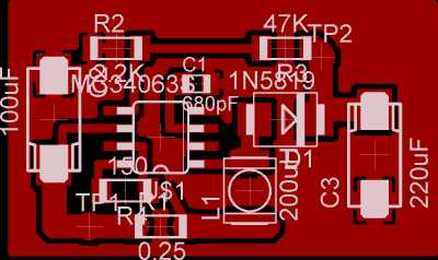
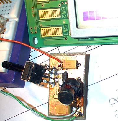
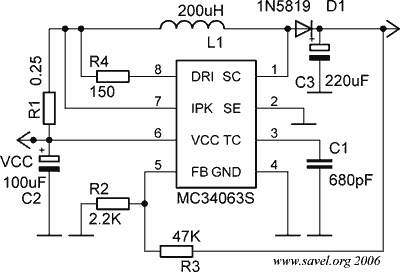
To start old Optrex DMC50264N LCD module you need to get +24V LCD bias voltage? Where to get it if you have only low voltage 3 … 5V? As LCD module drains very low current, it is possible to build very small DC/DC converter. There are lots of chips designed for this. I used MC34063, as I already had few of them in some old trash boards. The schematics are typical, used from datasheet. As the current is very low, it is possible to use very small SMD inductance. I didn’t find very small, so I used quite big- about 1cm tall… 🙂
Components used in my testing board: C1- unknown, C2- 330µF x 10V, C3- 10µF x 35V, R1- 1Ω, R2 and R3- trimmer, R4- 180Ω, L1- unknown, D1- some smd shotky diode…

PCB board for printing in pdf format.

When the voltage and LCD contrast is regulated, just measure the resistance of trimmer and use the values in R2 and R3. As MC34063 is quite powerfull chip: 3V to 30V Input Voltage Operation and internal 1.6A Peak Current Switch, the output current can be increased- just use proper coil and diode. Also use proper cooling for whole device. But remember that SO device can handle only 625mW (DIP- 1W).


Hi –
Just finished building your pcb for the MC34063 – worked like a charm (Once I turned the diode the right way around 🙂
thanks for posting ( in english !) and keep up the good work,
/holger
Holger Morgen
Denmark
I don’t know what diodes are you using and what are you building… But this circuit is exact as in datasheet. Also, it is working in real world.
this is copy from on-semiconductors datasheet.
oh, nono sorry – You diagram and PCB are 100% OK! ; It was just the SMD diode (1N5819) I got, was not marked very clearly, so, even after measuring, I did it wrong.
(stupid me 🙂
Thanks for you help,
/holger
“Administrator”: is not the same “literally.. Vi 28.
You’re too smart.