Bones

I forgot a bit “instruction of safe animal handling” and one small animal pressed me and my hand to the wall…

Bad horsy
My little Bad horse who pressed my hand.

And my hand turned to other side a bit. I even heard some crackle noise, but it was from the wall, as x-ray told the bones are ok. And the problem is only that everything what is possible to strech is over streched.

kauliukai triakst-triaks
My little hand.

So there will be some gap in this weblog, as I can not use soldering iron and chips with one hand. It is even hard to type with one hand when you learned blind-typing technics.

🙂

Posted in Personal | Leave a comment

Transformer for PSU

Ferrite core transformers are used in high frequency power supply. The main core parameters are core material and area of core cross-section. Area can be calculated using regular geometric formulas. The problem is to determine core material- they all look dark gray… But we can assume, that manufacturer used most common and cheapest core. So when cross section area and other physical dimensions are measured, we can adapt then to some datasheet.

Various ferrite cores

Another important parameter is air gap. The core can be ungapped and with some air gap. The gap size can be from some standard range, but sometimes it is specially made by rasping central core element.
Ungapped core is used in push-pull schematics- the core is force re-magnetized. Gapped core is used to prevent core saturation. The problem with the gap is, that all formulas and design software calculate core gap, ant there is NO software to calculate all other parameters when gap is known.

Gapped and Ungapped core

While making powerful transformers sometimes the wire is very thick. The diameter of either the primary or the secondary winding must not be larger than the recommended maximum (0.4 mm), for Skin Effect. Due to Skin Effect, the cross section of the wire may be under utilized, resulting in excessive heating of the windings and thermal related transformer failure. The thick wire is replaced with few smaller one winded at once, or using special multithread wire. If the bare conductor diameter of the wire is larger than that of the 27 AWG for 132 kHz or 25 AWG for 66 kHz, a parallel winding using multiple strands of thinner wire should be used to minimize skin effect.

In older and very powerful PSU I found copper foil used instead of wire.

multithread wires
Replacement of thick wire

Number of windings in transformer can be calculated using special formulas of special software. Here you can see the output of special transformer design software. It was downloaded form semiconductors manufacturer’s site for free.


Output of transformer design software

Posted in Anything | 2 Comments

High power PSU (2)

The main component of PSU is TOPSwitch-GX chip. There are produced whole line of these chips: TOP242 (weakest), TOP243, TOP244, TOP245 (used in this design), TOP246, TOP247, TOP248, TOP249 and TOP250 (Most powerful- 10A switch, up to 290W output power).

The chip is connected in typical way according to manufacturer’s recommendation. Eagle schematics is a bit skew, but it is useful and working. I highly recommend to read all application sheets for manufacturer’s site.

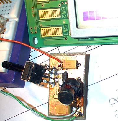
R2 resistor is already discussed in older post. Other important elements in live side are R1, D1, D2 and C2. C2 must be high voltage one, not less than 400…500V. Interesting diode D2 is P6KE170. D2, C2 and R1 are used to protect chip’s output drain for overvoltage spikes. It is leaking inductance clamping circuit. C2 and R1 are selected such, that D2 dissipated very little power except during overload conditions.
R1 is 2W power resistor. D1 is 1N4937 and is not recommended to use any other cheaper alternative. It is fast recovery rectifier, 600V, 1A (pulse 30A)

R10 sets the device current limit to 80% of typical to limit overload power. So, if your transformer and output diodes are powerful, you can short circuit PSU without any problems.

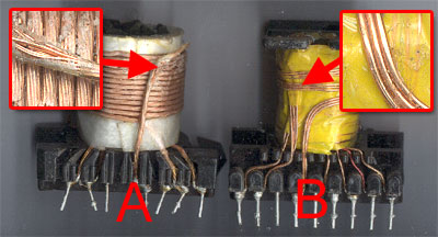
Bias current for optocoupler in live side is fed from special winding of the transformer. It is very low current, 12V winding, so the wire can be very thin. And diode D5 is very small.

The control pin components (C5, R4, C6) are not very clear for me. C6 is high frequency filter. And the rest is something used during startup. In datasheet there is the line: CONTROL pin capacitor: 47 μF, 10 V, low cost electrolytic (Do not use low ESR capacitor). But the donor PCB from some LCD monitor is with cap which looks like low ESR…

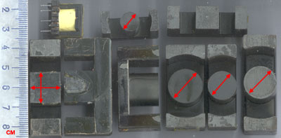
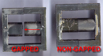
Now let’s look at the transformer.

Posted in Anything | Leave a comment

High power PSU

This is simple, quite powerful and economical power supply. You don’t need to switch it off- when load is off, the psu draws on fraction of Wat of the power. (80 mW @ 110 VAC, 160 mW @ 230 VAC). The main component is TOP242-250 chip.

Special transformer is used in this supply.

Circuit diagram
Schematics for printing and viewing.

The schematics is universal. It is possible to change output voltage and number of outputs. Also it is possible to change the power of whole power supply. When using most weak chip in closed box without ventilation, it is possible to build 10W power brick. Using most powerful chip and proper cooling- the power increases up to 290W!

The schematics consist of few main modules:

Live side rectifier and filter. It is used to produce high voltage DC and to filter all possible interferences.
Strange resistor near C18 is NTC resistor. It is used to reduce current spike when device is plugged into mains. C18, TR1, CX and C3 are used to filter all high frequency stuff from and to the device. If device is made in Chinese way, all this stuff can be omitted. R12 (the symbol in circuit diagram is bad) is varistor. It is used to protect the device from voltage surge. If voltage is more than 270V it shortens the mains and fuse blows. We can add R2 to the protection circuit. When voltage in DC side is more than some value defined by R2, the top switch chip is switched off.

PCB

As you can see from PCB image, some duplicated devices (like F2 and F3, CX1 and CX2) are place on on others top. This makes PCB more universal- it is possible to use different size devices. Additional chokes (L6-L9) are just simple jumpers. It is possible to make PCB without them, but some traces will become much narrower and longer. And this PCB is designed to be with thick tracks. So everybody can make it using all simple PCB making technologies.

PSU

Side view of the PSU. That trimmer is used to adjust output voltage. When PSU will be tuned, the trimmer will be replace with simple resistors.

Continued…

Posted in Anything | Leave a comment

Step Up PSU for LCD

To start old Optrex DMC50264N LCD module you need to get +24V LCD bias voltage? Where to get it if you have only low voltage 3 … 5V? As LCD module drains very low current, it is possible to build very small DC/DC converter. There are lots of chips designed for this. I used MC34063, as I already had few of them in some old trash boards. The schematics are typical, used from datasheet. As the current is very low, it is possible to use very small SMD inductance. I didn’t find very small, so I used quite big- about 1cm tall… 🙂

circuit diagram
Schematics for printing

Components used in my testing board: C1- unknown, C2- 330µF x 10V, C3- 10µF x 35V, R1- 1Ω, R2 and R3- trimmer, R4- 180Ω, L1- unknown, D1- some smd shotky diode…

component placement
PCB board for printing in pdf format.

Small converter for LCD bias

When the voltage and LCD contrast is regulated, just measure the resistance of trimmer and use the values in R2 and R3. As MC34063 is quite powerfull chip: 3V to 30V Input Voltage Operation and internal 1.6A Peak Current Switch, the output current can be increased- just use proper coil and diode. Also use proper cooling for whole device. But remember that SO device can handle only 625mW (DIP- 1W).

Posted in Anything | 5 Comments

PCB and Schematics software

One of the popular programs for PCB tracing and circuit diagram drawing is Eagle from Cadsoft. The software is available for Windows, Linux and Mac operating systems.

PCB and Schematics editor Eagle

Freeware version of software has some limitations: The usable board area is limited to 100 x 80 mm (4 x 3.2 inches), only two signal layers can be used (Top and Bottom) and the schematic editor can only create one sheet.

But such limitations are not very bad for novice and amateur users. You can download the software from site at: http://www.cadsoft.de/ .

The component base are quite big. There is user exchange ftp in the site. And it is very easy to create new element by yourself.

The bad sides of the program: autoroute functions is very dumb. No autoplace function. And one problem with pads and holes. Some elements have very small pads and I can’t increase the size without editing library.

Posted in Anything | Leave a comment

Security Video

Got some bad security video cameras for recycling. Few color ones made by Philips, two Sanyo and others KC-263C and KC-383C. It is mid and high resolution black and white CCIR video cameras.

Pokemonas ir Video kameros
Security cameras’ bodies and some generic brown Pokemon.

The KC263 and KC383 are powered from the mains power. It can handle 85…265V AC. And the problem in these cameras is that power supply is very ugly made. The problem is with 12V output capacitor. It is 1000µF x 16V low ESR capacitor. Manufacturer used cheap product and all the caps were blowed up like in computer main board. As voltage is only 12V, I decided to use capacitors from mainboards. I needed to drill extra hole and use much bigger cap. But now I can use 1000 or even 2000µF caps x 16V.

Even camera with missing PSU is repaired. I is working from my computer PSU.

About color philips cameras (LTC 0450/51). The problem is same. But as power supply is much more complicated, I need to replace 9 capacitors: 8 @ 10µF x 35V and one 220µF x 6.3V. Small caps replaced with exact ones, big was replaced with 1500µF x 10V from computer motherboard and made by Sanyo. Both color cameras are working…

Also there are two cameras from Sanyo. They are powered from external 12V PSU. One camera is dead (internal converter), other is working.

Posted in Anything | 5 Comments

Tuning Audio Amp

Connect pulse generator from older post to your audio amplifier. Set volume to something in the middle. Connect oscilloscope to the output of the amp with dummy load.

You will not see ideal square signal in the output, but all these distortions can describe your audio amplifier.

As there are lots of images in this post and big table. So press on the link to read more about audio amp tuning…
Continue reading

Posted in Anything | Leave a comment

Pulse generator

For further audio amp analyze we need square waveform generator. I can use my generator, but we can build one using very common TTL chips. We can use any 74XXXX chip which can be combined to “NOT” logic element. Most common chip is 74LS00. In my breadboard I used 74LS04… I used all idle “NOT” elements to buffer signal.

Square form generator circuit

When powered, this schematics generate square form signal. Now, some theory:

Square waveform

In the right, red picture is undistorted square pulse. There are three main parameters: Umax, T and ti. Umax is amplitude of the signal. T is – time, the length of waveform. You can calculate frequency (in Hz) from this: f=1/T. (if you measure in ms, don’t add all zeroes, just add k to the result. Same when using μs- the result will be in MHz).
ti -pulse length time. Another useful parameter is pulse duration ratio T/ti. In red picture it is equal to 3.

This is theoretical waveform. The real waveform (a bit artificially distorted) looks like in green image. There are additional parameters: tf and td. tf – leading edge time (pulse front), td – trailing edge time (pulse decay).

Umax is measured without taking any attention to all small spikes. ti is typically measured at 0.5 Umax (sometimes 0.7).

From Радио №9, 1989.

Posted in Anything | Leave a comment

Real Output Power

How to measure real output power of audio amplifier. Sometimes on some cheap audio devices you can see magical numbers like 1000W or something, and device is handheld. It is not real power, it is bullshit.

Attach dummy load to audio amplifier load. The resistance of the load must be equal to resistance of your speaker. Power dissipation of your resistor must be equal to your guessed audio amp power. Set your tone generator to sine wave and frequency to about 1000Hz. Connect oscilloscope to your load. And turn your audio amplifier and audio generator volume up until you’ll see distortion in the picture.

Measure real output power

And now time for some math.

P=(U/2.82)²/R

In this example: R=4Ω, U=6V. P=1.132W

This was the power of my second tube amplifier. Audio amplifier is not fine tuned.

Posted in Anything | Leave a comment