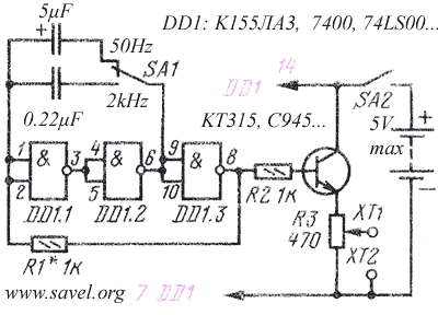
For further audio amp analyze we need square waveform generator. I can use my generator, but we can build one using very common TTL chips. We can use any 74XXXX chip which can be combined to “NOT” logic element. Most common chip is 74LS00. In my breadboard I used 74LS04… I used all idle “NOT” elements to buffer signal.

When powered, this schematics generate square form signal. Now, some theory:

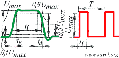
In the right, red picture is undistorted square pulse. There are three main parameters: Umax, T and ti. Umax is amplitude of the signal. T is – time, the length of waveform. You can calculate frequency (in Hz) from this: f=1/T. (if you measure in ms, don’t add all zeroes, just add k to the result. Same when using μs- the result will be in MHz).
ti -pulse length time. Another useful parameter is pulse duration ratio T/ti. In red picture it is equal to 3.
This is theoretical waveform. The real waveform (a bit artificially distorted) looks like in green image. There are additional parameters: tf and td. tf – leading edge time (pulse front), td – trailing edge time (pulse decay).
Umax is measured without taking any attention to all small spikes. ti is typically measured at 0.5 Umax (sometimes 0.7).
From Радио №9, 1989.
