Well, it’s New Year again. Probably, 2022 in a row since some event. Or 5782. Or 1443. Or Reiwa 4. Or maybe 7530? Or maybe 4720. For me, it’s probably about the 50th number…
So, the number doesn’t matter. What matters is that the days are getting longer. And on this occasion, you can wish something for yourself and others and make promises. Like that there will be no mess on the table… 2022 New Year … or it will be even bigger.
So I wish that the mess on the table does not bother you at all, that ideas are generated non-stop, that the hobby brings good mood, that everything goes more fun and successfully. I wish everyone happiness, health, and love in the upcoming numbered year.
Yesterday, I wanted to open an old file and pfff…. A quick analysis showed that the disk is dying, although SMART says everything is fine. Shit. But it’s a good opportunity to talk about how my disk farm is organized. I have already written that my home computer’s disks are gradually migrating to smaller ones. The disk that just arrived was large (in every sense), but now it will migrate to smaller ones.
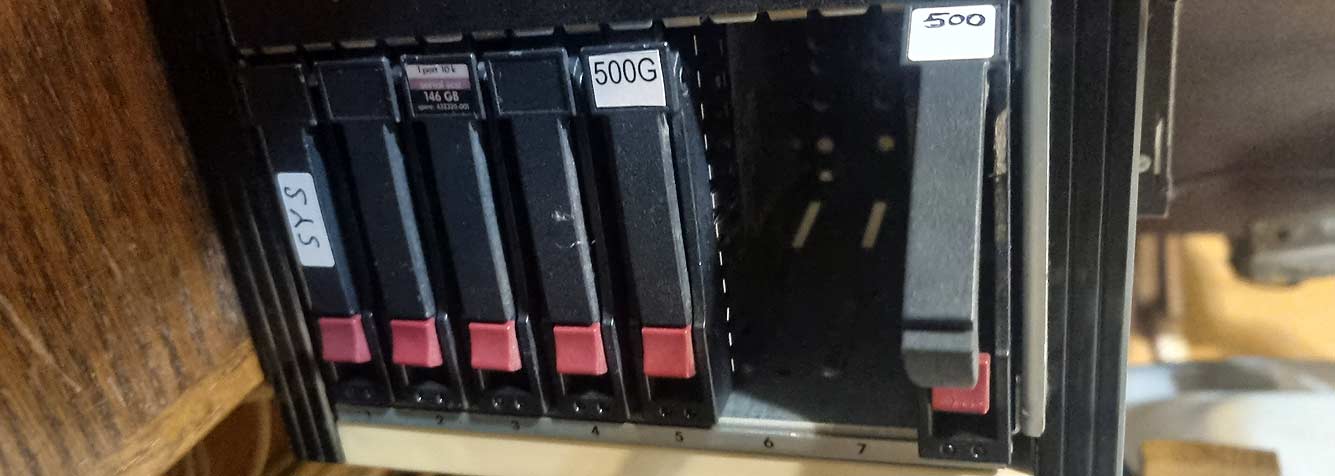
Mechanically, it’s a basket from some server. It was designed for SAS disks but is mechanically and electrically compatible with regular SATA disks. I just had to re-solder the cable to connect it not to the SAS RAID controller but to a regular SATA controller. Disk #1 is the system disk, a Samsung SSD. Disks #2, #3, and #4 are Disk X, a simple stripe RAID for temporary files (where standard TMP/TEMP and various programs’ SCRATCH files fall). Disk #5 with the 500 sticker is the new ‘My Documents’ disk. Disk #8 is not inserted.
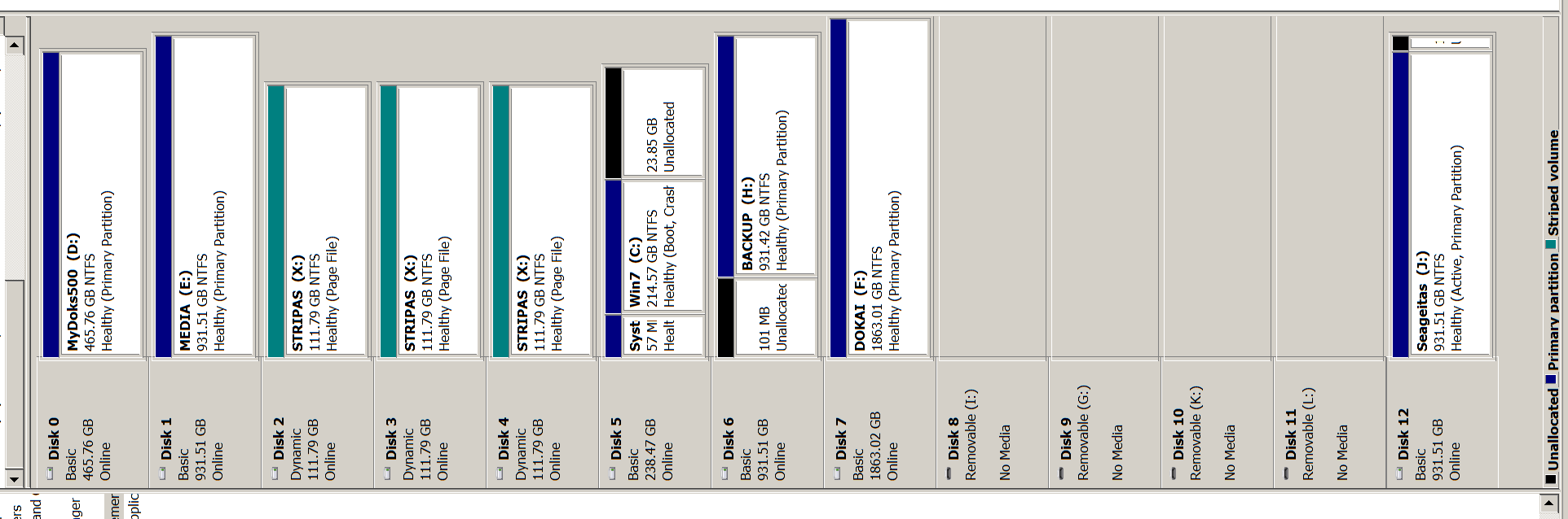
The whole chaos looks like this:
There are also the old ‘My Docs,’ ‘Media,’ and ‘Backup’ disks. They are currently of large format. The ‘Steam’ games disk was removed because document copying was being done at the time of the picture. And disk ‘J’ is a backup disk connected via USB – I was looking for a copy of the corrupted file. The ‘Backup’ disk is intended for Windows’ own backup. However, it is almost useless. I constantly find that the backup did not happen or something similar.
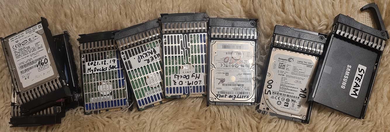
Here’s how the floppy collection looks. I liked the basket’s mechanics, so I collected handles. And where do the disks come from? Well, when you change the working laptop disks to SSDs, you format the disks and use them. And they got collected from somewhere. That’s why they are so small – old and ‘working’.
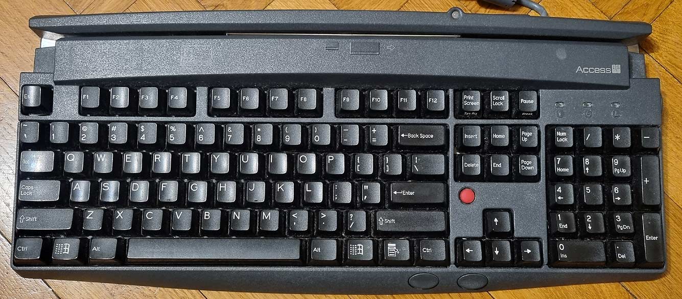
Those who have traveled by air will probably recognize these keyboards. This is an industrial-level keyboard with ‘cherry’ keys and add-ons.
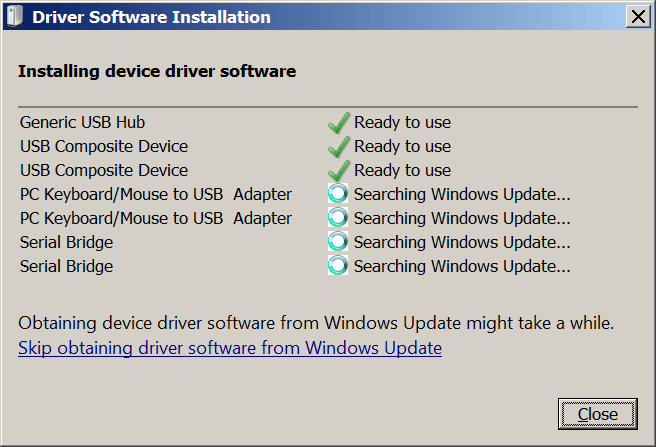
This also shows that Windows was very happy when I connected it to the computer.
This is a multi-device: keyboard, mouse, magnetic card reader (4 tracks), optical scanner (reads and OCRs text from personal documents where many ‘<<‘ symbols are printed). Also, there is a USB to RS232 conversion and, in this particular model, an ultra-slow and limited USB hub.
The keyboard is old, so the electronics are somewhat archaic. And its software is completely tragic. Theoretically, everything is connected as serial ports (mouse and keyboard – HID). However, it uses special drivers, so neither the OCR nor the card printer appear as standard devices. Special drivers and special software convert the information to another virtual COM port. Then, you can read information from cards or OCR. The information is contaminated with ‘service’ data and is not convenient to use. A similar problem occurs with 2D scanners from the same source – they are not usable in the household without serious hacking.
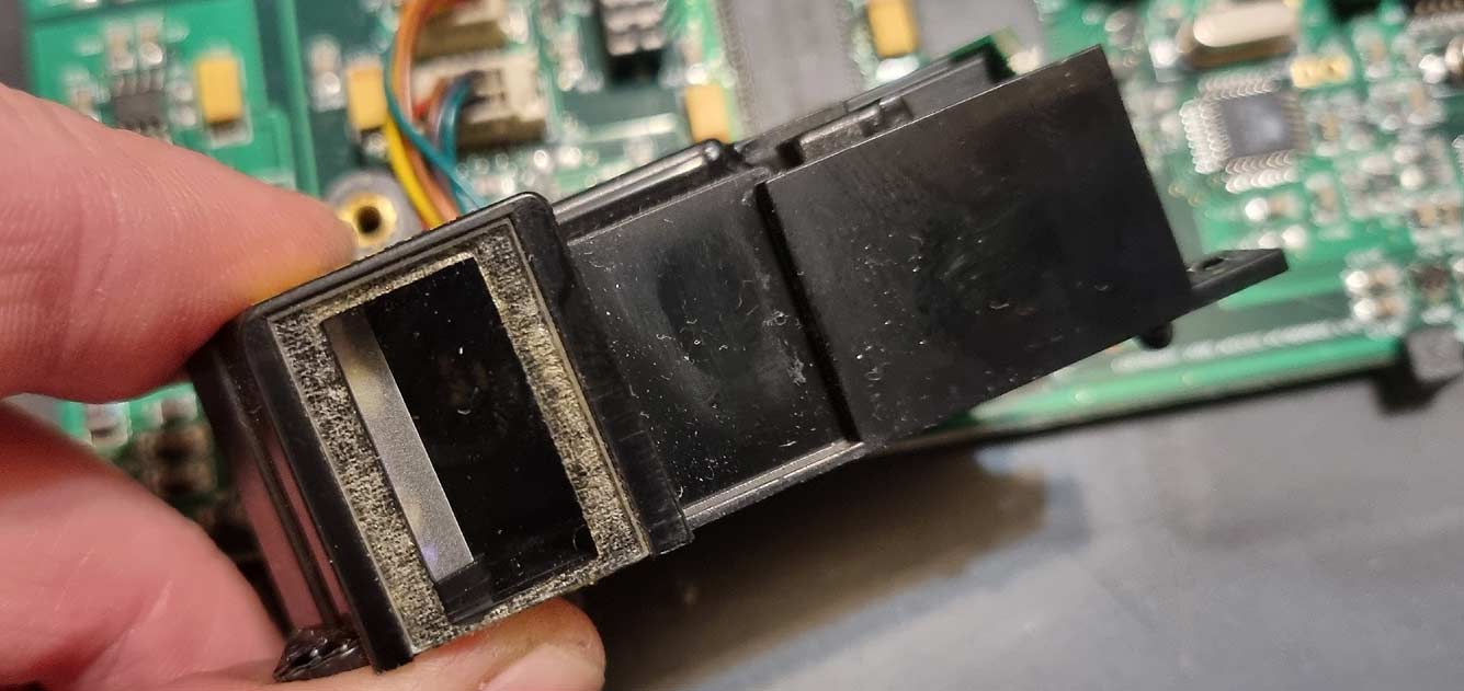
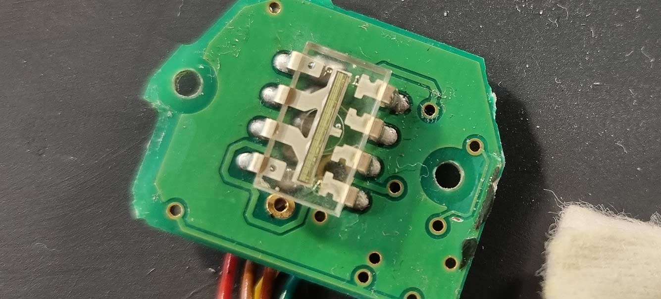
The optical ‘eye’ that reads documents. It also has LED lighting.
Unfortunately, such a detector only reads images. You won’t collect many pixels here.
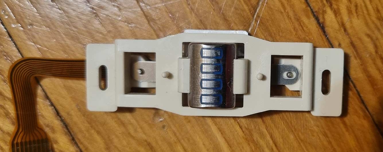
The magnetic head with 4 tracks. It read all the magnetic cards I had, from payment cards to Maxima discount cards. My ‘Ačiū’ card reads very poorly in the store itself. However, the problem is definitely not in the card, because this keyboard read the data perfectly no matter how I swiped – quickly, slowly, or in any direction. I think the readers in Maxima are clogged and worn out.
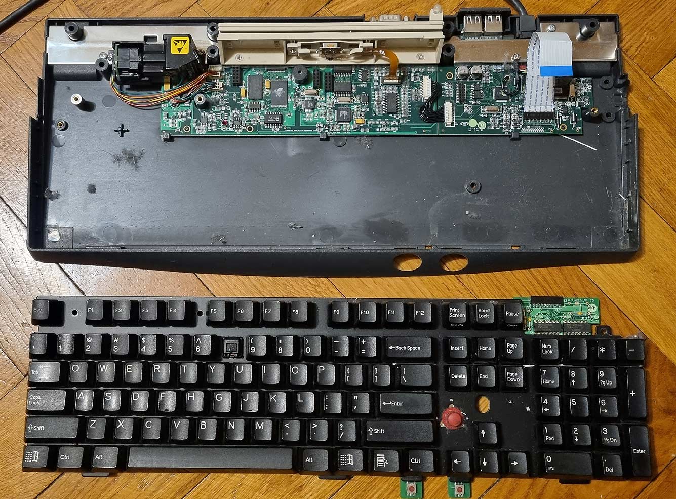
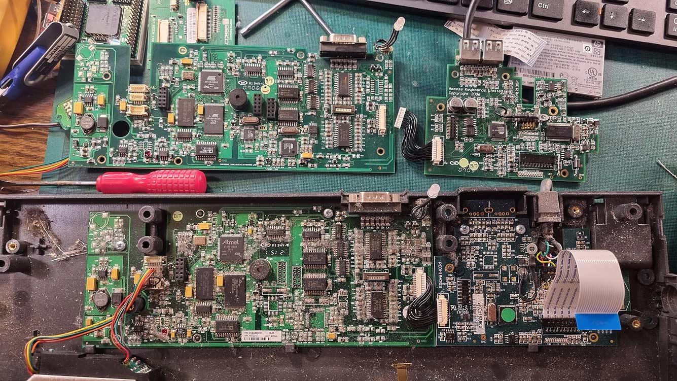
I liked the USB hub, which, although very slow, allowed me to connect a mouse to the keys. This keyboard had a broken key, so when I took it apart, I broke everything. And unnecessarily, other keyboards do not have a USB hub. They are somewhat newer and simplified:
You can see that the place for the USB connections is prepared, but not filled.
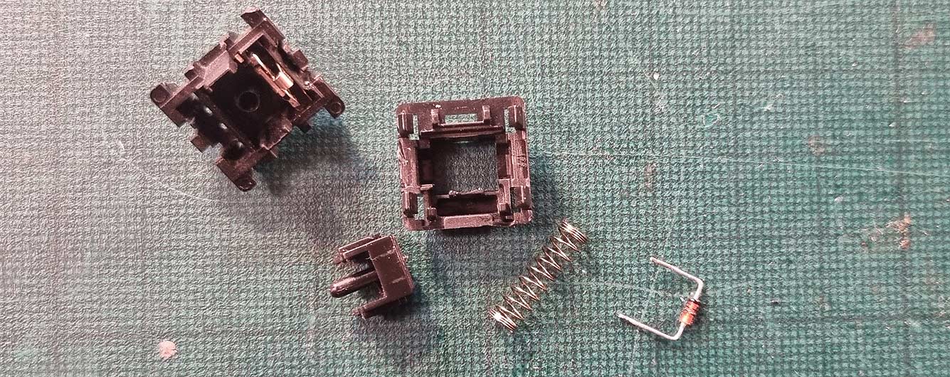
The button itself:
This is a full-fledged mechanical button and diode. The diode is used due to key chords – it protects against ‘ghosting,’ when pressing several keys simultaneously, some combinations cause unstressed keys to be transmitted. The diode isolates individual keys. I don’t know how this problem is solved in membrane keyboards.
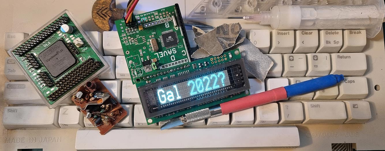
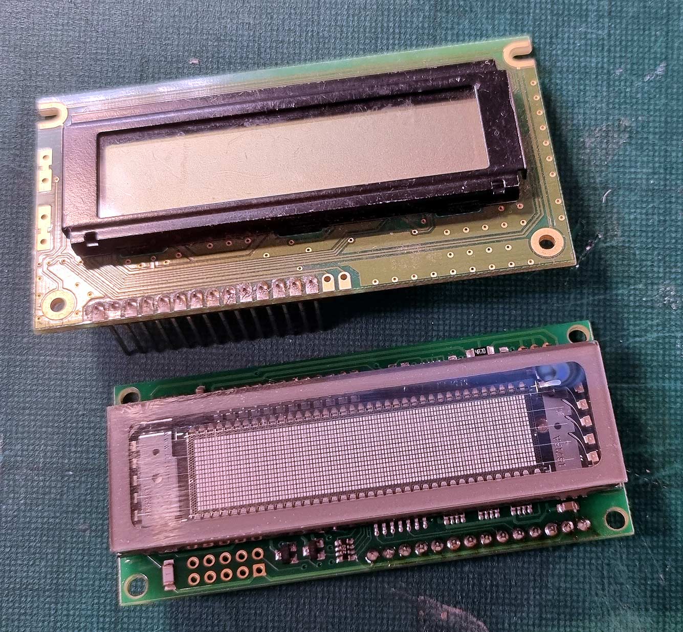
Lithuanian airports disposed of some equipment, and there were devices with VFD screens (the devices themselves were specific, with very strange software). At least I got the VFD screens: Noritake Itron GU112x16G-7806A V3. I think the software is suitable for the whole family, so I wrote GU140x16G in the title because I wrote it based on that datasheet. The VFD module itself is probably fully compatible with the LCD module, but additionally has graphic module modes. Therefore, any software (and hardware) that supports a standard LCD module with a 14-pin connector works perfectly with the VFD module. There is a small issue that the module initializes a bit slower, but most of the software works.
However, compatibility wasn’t great for me, but I liked the large (and small) font, drawing, bitmap sprites, inversion, and so on.
The software for the AVR family microcontroller (fully compatible with my ARM library) is written as a “wrapper” for the standard LCD module. You only need to add additional commands to the existing LCD module software, and you already have a luminescent graphic display.
My CO2 laser has been unused for a couple of years. Its tube degraded and started to weaken. About a year ago, it was still possible to cut paper and make some “applications.” Today I tried again – the tube lights up, but it doesn’t “heat” – it didn’t burn anything even a bit. The current through the tube is about 20mA, everything glows nicely, but it doesn’t lase. I took out the tube and replaced it with another one (which was like new, but I couldn’t test it well because the cooling system’s hoses had stiffened). I brought the old tube home – it will be the topic of an article. And I can still torture it before breaking it. I have the desire to apply alternating voltage to it…
No matter what the managers say, the power of a CO2 laser is directly proportional to the length of the tube’s resonator (and the tube itself). Theoretically, a tube with a thicker beam can be made, but the optics must be different accordingly, and focusing the beam is somewhat more challenging purely due to geometric laws. My tube is 40W max, its length between the mirrors is 67-70cm. The total length is about 80cm. You can’t push more watts into such a tube. And even 40W should be doubted.
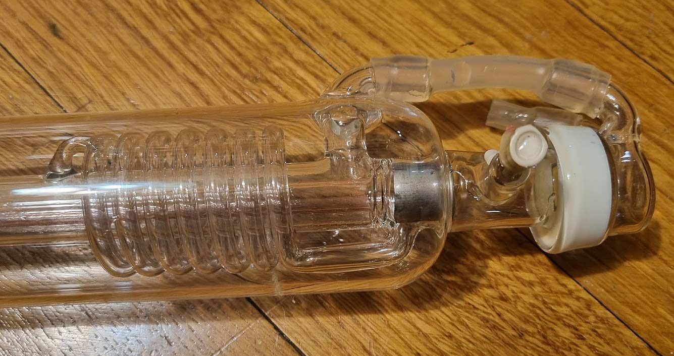
This article is purely illustrative; nothing will be damaged yet. But here, we will explain why there is a glass spiral at this end. This is the “blind” end with a full mirror. The latter is additionally cooled with water. The spiral is needed to ensure that the electrical discharge occurs only inside the tube, not outside. This results in the electrical path through the center of the tube being significantly shorter than outside. The large difference is also necessary because it is very hot in the center of the tube, making it slightly harder for the electricity to flow than through simple N-He-CO2 gases. What is the purpose of the external reservoir? CO2 gases get blocked after discharge, and the molecules need some time to rest. This happens automatically – the laser operates from a constant voltage, and the gases in the plasma move from one electrode to another, then exit to the external reservoir, where they cool, recombine, and so on. Older and more powerful lasers used to have (and maybe still have) external pumps and even the ability to replace the gases. My first laser that I disassembled (it was damaged by storage in cold conditions) was precisely the “open,” “flowing” type. There, higher powers are possible because the gases are forcibly mixed.
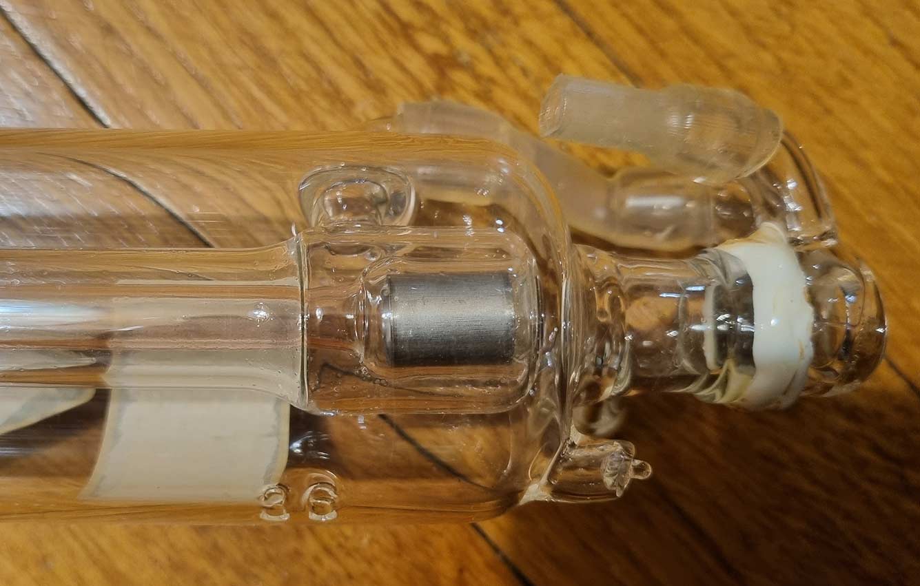
The other end. You can see the electrode and a slightly more complex mirror cooling. Here, it is impossible to cool the entire area – the laser has to “exit.” Therefore, the construction is somewhat more complex. By the way, this is the “negative” end.
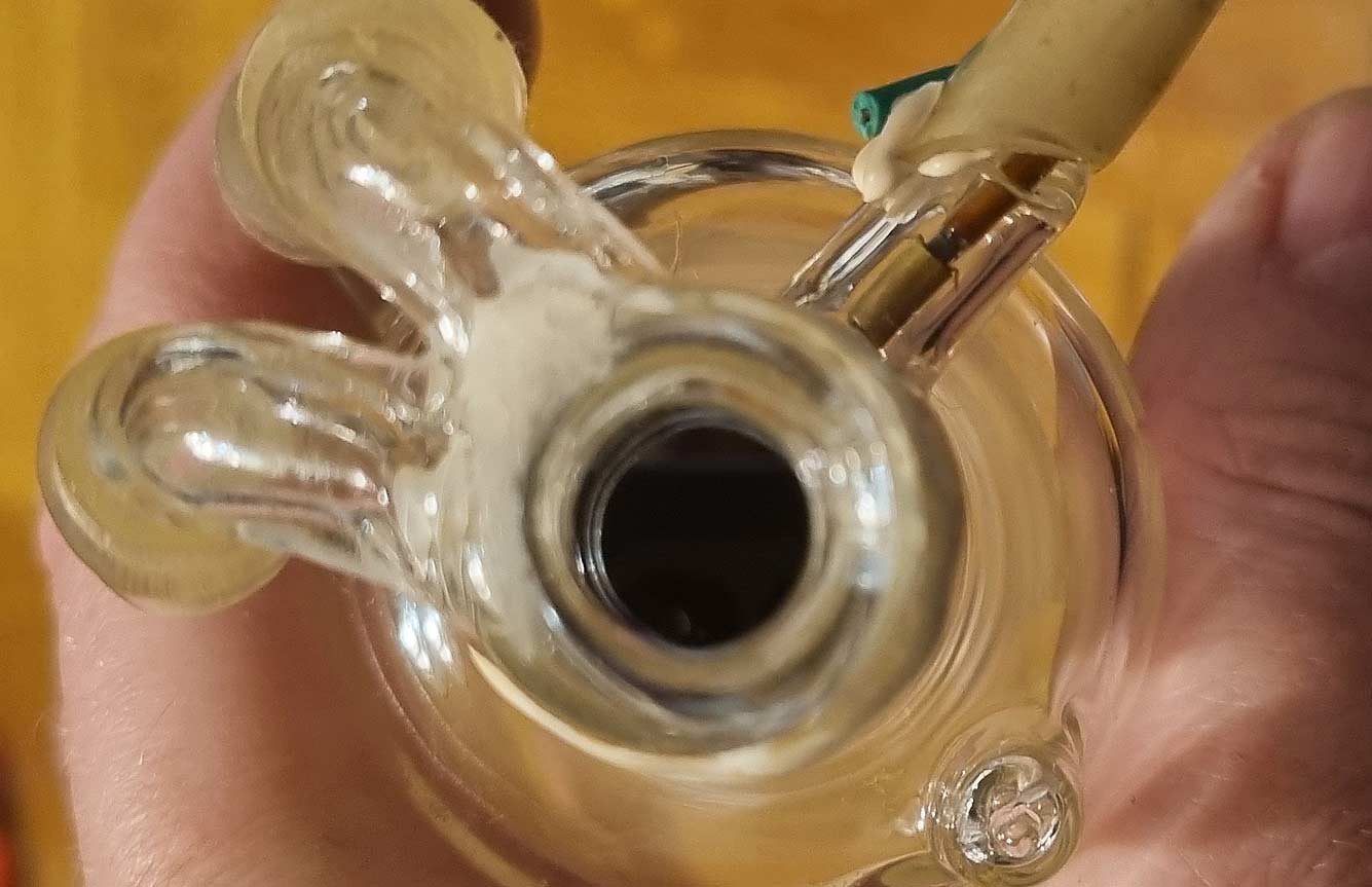
Here you can see the “half” mirror, most likely made of germanium. This mirror must be conductive to IR rays and withstand the effects of both the internal atmosphere and the external one.
What happened to this laser? I really don’t know – the electrodes don’t seem to have exploded. Helium definitely didn’t escape, and the plasma ignites perfectly. Either the mirrors have deteriorated, or the CO2 gases have disappeared somewhere (they can react with metal or glass. O2 corrodes with metal, and C settles on the walls). The inner tube has a purple tint – that’s normal, some special glass. The inner glass of a new laser is even darker and more purple.
For my latest collection exhibit, I decided to upgrade the power supply – to create something like the LM2596 from an overclocked 7805…
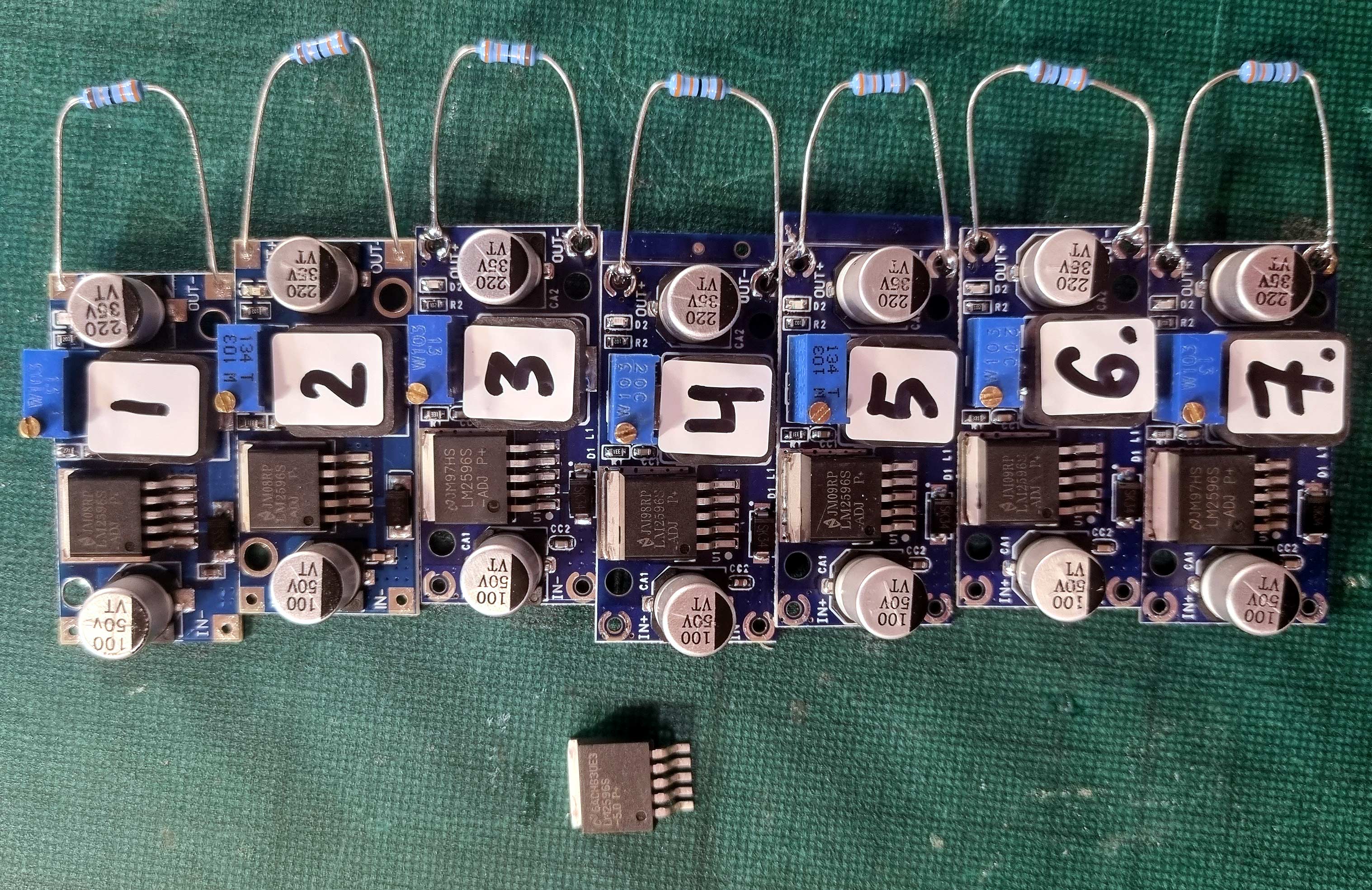
Before the postal service went crazy, I bought the cheapest PCBs with counterfeit LM2596ADJ from several suppliers: LM2596 modules from China (photo enlarges, you can look at the chip logos)
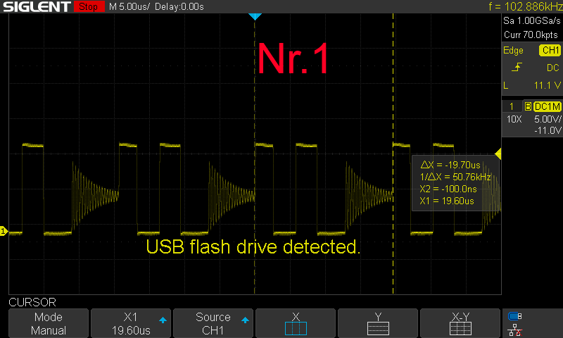
To test, I connected them all with the same load (about 33 ohms) and adjusted them to 5V. Input voltage 13V. Some modules operated at around 50kHz frequency – likely an analog of a weaker chip (LM2576?). Others worked at the correct frequency – around 150kHz, though perhaps a bit more.
One module worked very strangely:
So I removed the chip and connected a salvaged (and maybe original, National-made LM2596S ADJ). I’m not sure about this chip, the inscription looks very unprofessional, but the PCB was assembled in Lithuania and used in some industrial computer. I also replaced the diode. I wanted to use a really original chip, the one nearby in the first photo, but I needed an ADJ.
Oscillograms of all modules. The calculations in the document mean almost nothing because the load is very small. However, if it is the LM2576, the inductance for this chip is probably too small.
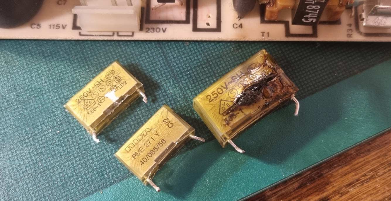
Anyone somewhat involved with old electronics will eventually encounter RIFA capacitors and their tendency to catch fire. I finally experienced it myself – a peculiar device was working, and I had to walk the dog. When I got back home, the room smelled like burnt sugar. I had to disassemble the device, and here’s the reason:
The larger capacitor with a hole was between the live (L) and neutral (N) wires. The other two capacitors connected these wires to the ground (PE). As seen in the photo, the main issue with these capacitors is their transparent plastic. Over time, it cracks and lets in air moisture. After some time, just boom, and the room is full of smoke. Nowadays, capacitors are not very necessary, but if we replace them, the larger one must be X-class (or better), and the smaller ones Y-class.
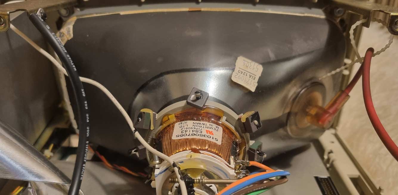
And to make the message longer, here’s another photo: ultrawide CRT Yes, that’s an “ultrawide” CRT. It’s precisely because of this format that I wanted to get this device. However, there will probably be an article about it another day, or maybe just a new page in my collection on the website.
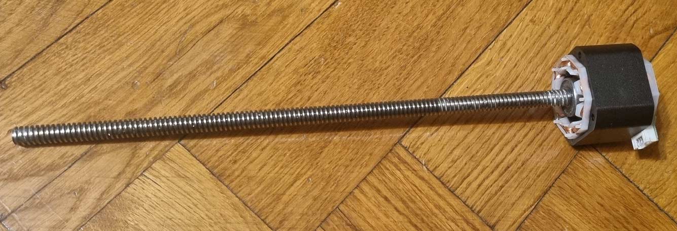
Somewhere, I mentioned that I have a photolithographic (UV-curing resin) printer. But I never mentioned that when I first bought that printer, my relatives decided to move it to another place without my knowledge because it smelled very bad to them. And the printer had resin in it… As a result, it was a complete disaster, and resin spilled everywhere, including inside the printer. After half an hour of shouting and maybe three hours of cleaning with paper, alcohol, and some foreign “some kind of mother’s” solution, I managed to clean the printer. As far as I could see, the resin did not get into the optics, the case was cleaned, and the electronics got an additional insulating layer. The printer continued to print correctly, but its appearance was no longer as it should have been. Today I turned on the printer after about five months and realized it was a disaster. The Z-motor was completely stuck. Apparently, the resin got inside the motor and finally hardened. It hardened so much that when turning with pliers, the metal screw was scraped first, and only then did the motor move a little.
Here is the motor itself without covers, as I thought the resin glued the bearings. Unfortunately, it didn’t. You can see the working area of the screw, so we grabbed the non-working area with pliers and scratched everything there.
This motor is a 17-size NEMA standard. There was no sticker on it.
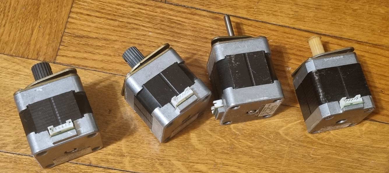
Here are some old NEMA17 motors with different winding parameters.
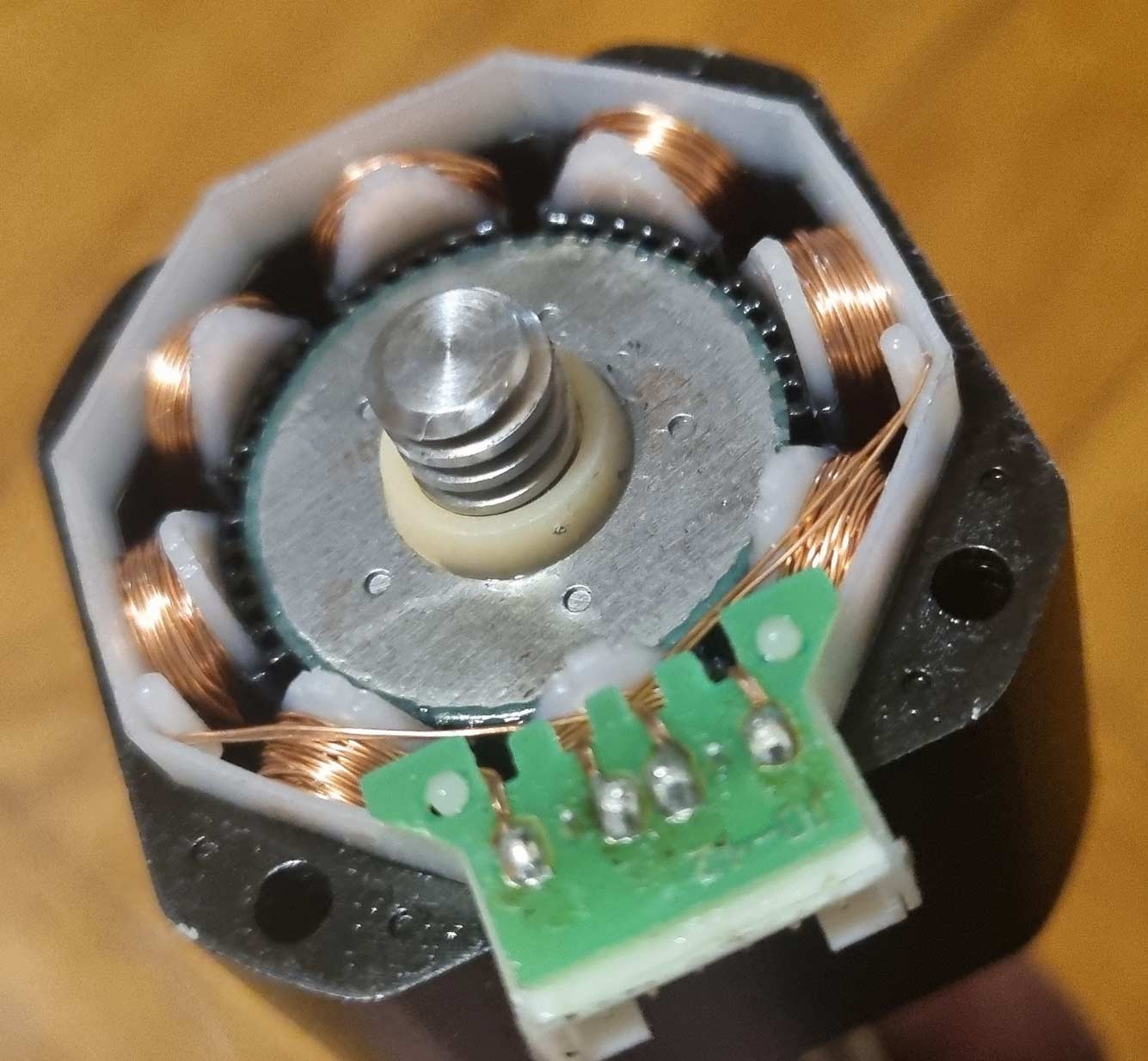
Their pinout is more or less standard, showing with an ohmmeter that the connection is the same. However, the old ones had a tap from the winding centers. In the Chinese one, this contact is not connected at all:
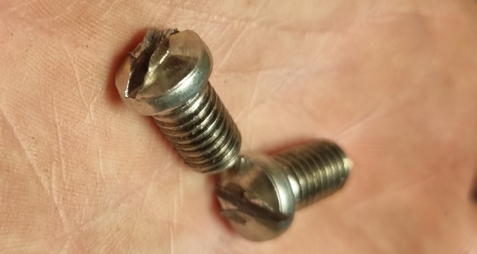
Another detail – in the Chinese motor, the 8mm screw is just pressed into the motor. There is no coupling (muff) between the motor and the screw. This means that any motor cannot be connected without turning works. It’s either a new motor or a new printer. Trying in various ways, I couldn’t loosen this motor; it was seriously stuck. Even when connected to a lathe and spun well, the motor heated up, but the resistance did not go away. The only option left was to buy because, according to all legends (and practice with old motors), when you disassemble a motor, its “mojo” – voodoo spirit (not to be confused with Mojo Jojo) evaporates. More seriously, some magnets lose their magnetism if their magnetic lines “open.”
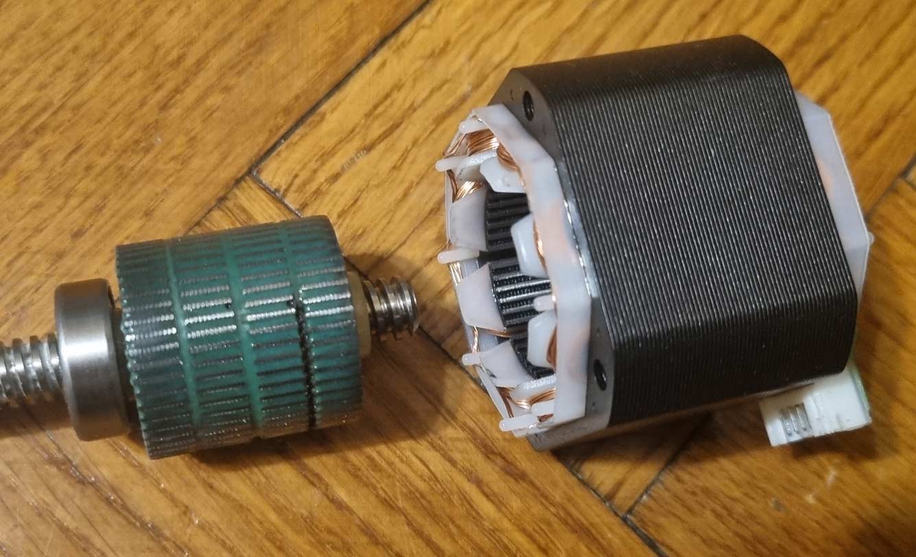
However, the motor was as good as thrown away, so I got brave and disassembled the motor completely:
Either I was lucky, or this is some new model with neodymium magnets that don’t lose their spirit so quickly. So quickly (just in case), I sanded the resin layer from the rotor with sandpaper, and the motor started to rotate relatively freely, but the “catching” effect remained – the magnet was still strong. I was lucky because once I disassembled an old motor, and after disassembly, it started to rotate very easily and lost its strength.