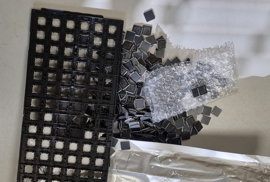
A good person reported that they brought some chips. But somehow there was no time—work piled up. After a few days, I went and saw the remnants….
It even squeezed my heart…
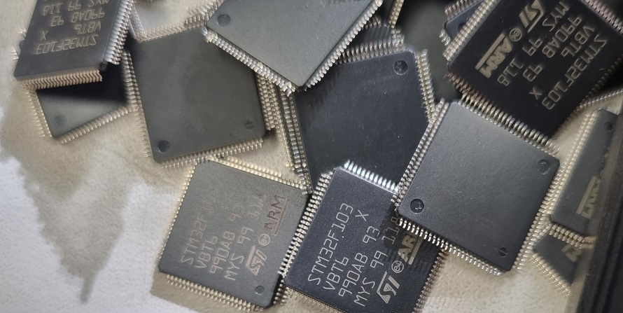
STM32F103VBT6: Medium-density performance line ARM®-based 32-bit MCU with 128 KB Flash, USB, CAN, 7 timers, 2 ADCs, 9 communication interfaces. 20KB RAM.
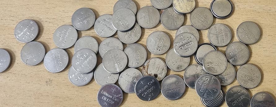
Here are the drop-chips, you can see the legs are slightly bent. Now I need to design a universal PCB. If anyone needs some, I can scoop them up. I hope they are good and not counterfeit.
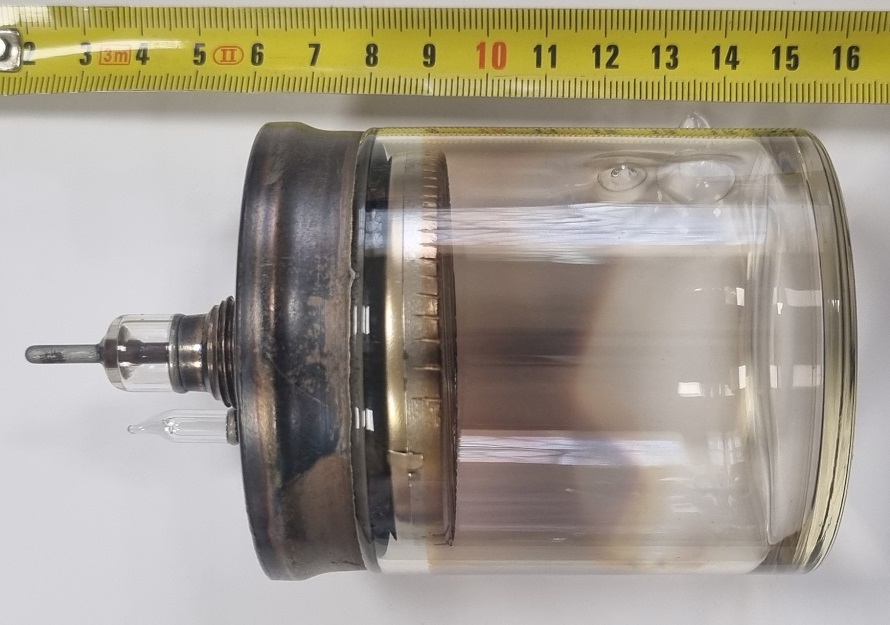
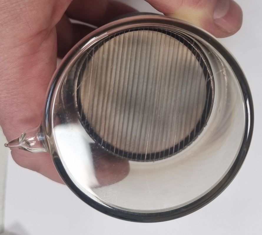
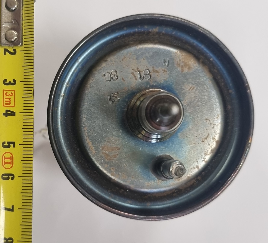
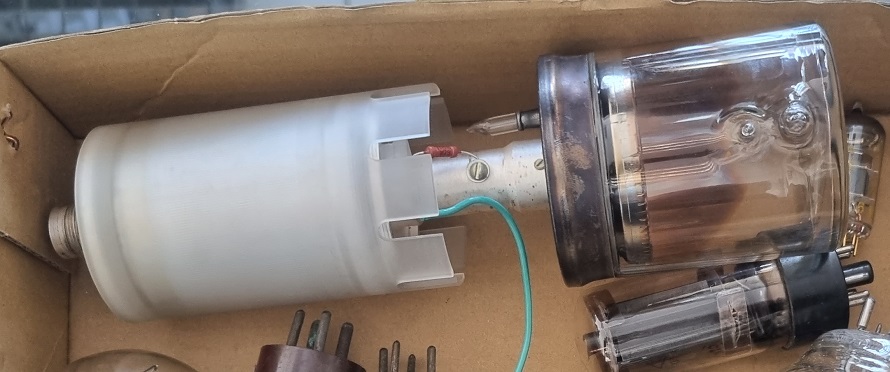
A rather unusual bulb came into my hands: bulb Only two contacts. Based on the design, it looks like it could be a photo or some particle detector.
Applying around 4kVDC causes a discharge inside the bulb. This means the working voltage is lower.
The inscriptions don’t say much, most likely either serial numbers, batch numbers, or production dates.
The bulb itself was connected with a coaxial connector, and where it’s white, there’s a “homemade” mylar capacitor between the contacts. Quite strange, as higher current in the bulb’s electrodes caused spots—the coating fears discharges.
If anyone has handled similar bulbs, please share your thoughts.
You go to the countryside for a bit, and when you come back home, you notice changes in the landscape. No wonder those suspicious old men were hanging around. Why on a Saturday?
One of the remaining antennas of the “Stalin’s organ” or jamming station (Object No. 603) is gone. It had been unused for a while because mobile phone technologies had changed, and such an expensive piece of land in the “rich” area of Kaunas was definitely tempting for various business people. Although the plots of land were “distributed to deserving people” many years ago, I think a mistake was made here. Of course, the “honorable people” sold the land, and now that the pole is gone, they will soon build a small residential area.
It would have been better to establish a park here—especially since beautiful oaks with low and wide branches remained, as the area had been free from human activity for many years. There was a pond, ducks lived there, and owls nested in the trees… The plot was unique because it didn’t need to be returned to anyone, neither to descendants nor to holy Jewish bones. Just a piece of state land. Unfortunately, the business was done long ago.
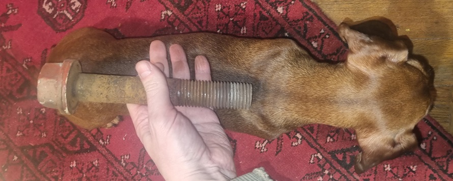
Some parts were unscrewed, some had to be cut with a grinder, and some were cut with an autogen. First, they removed all the bolts and replaced them with new ones. Then somehow they technically brought it down. Unfortunately, I didn’t see it.
They laid the pole down “whole.” The first one was dismantled in two stages. There was probably free space.
There are still two left. I don’t know if the TV pole will be demolished, but the other one will definitely be torn down. Because instead of this piece of nature, several multi-story buildings and, of course, many car parking spaces will be built.
You can read more about the station only in the internet archive… Web Archive Link
The jamming station consisted of three towers with antennas between them (ВГДШ). Sometimes the antenna wires would break and spark seriously. Then even Mayak would stop playing due to the pulses. The electric field was strong; a simple voltmeter would show a voltage between the segments of the iron fence. My first electronics experiments (building radio receivers) always ended in failure because the direct amplification radio receiver would only pick up the nearby Mayak broadcast. Once I even heard Mayak through an unplugged speaker. This only proves that 5G doesn’t scare me.
A more interesting element was the feeder, which was about 2 or 3 meters high—several wires on about 30 cm long insulators. One insulator should still be hanging in my yard under the ivy. Somehow, I instinctively stayed away from it when crawling around that forbidden area.
P.S. The size of the bolt, compared to size of my small dog.
For several years now, Olympus has not been able to make decent software. Even the most elementary errors are still not fixed, and don’t even ask about the graphs. In my work, I sometimes need to compare the entire XRF spectrum—like comparing the “fingerprint” of a material. Not just compare but also highlight important zones, add markers, and, of course, print it nicely or export it to a PDF file. All the software was written in about five evenings and purely “for fun.” In the process, I learned a bit more about .NET capabilities.
To use the program, you need to somehow export the XRF spectrum to a CSV file. That doesn’t work immediately either, but you can overcome Olympus’s foolishness and somehow extract the data. Then you need to remove the first 40 rows and the first column (maybe I’ll make automatic import later).
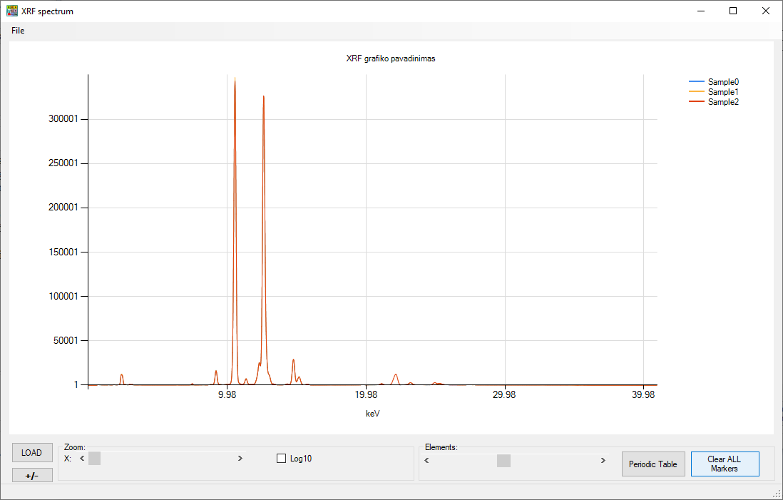
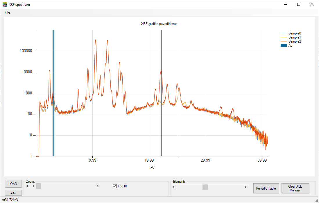
A working example with three materials that are very similar. The “standard” graph seen in the original software looks something like this:
In the old version of the original software, which only runs on XP, there was a logarithmic scale. So we made a logarithmic scale:
You can see an anomaly at the silver. Knowing that these materials are declared as identical, it is clear that someone is slightly cheating. One material is very poor catalysts, the other material is the same catalysts but with burnt capacitors or some other catalysts added. Probably nothing malicious, but “non-standard” materials sometimes affect quantitative XRF analysis (compared to ICP) and all kinds of “bad things” start, like poor measurements or similar complaints. And when you “magically,” like Sherlock Holmes, say—dear sir, did you perhaps pour some “condensers” into the general barrel? Everything gets sorted out immediately.
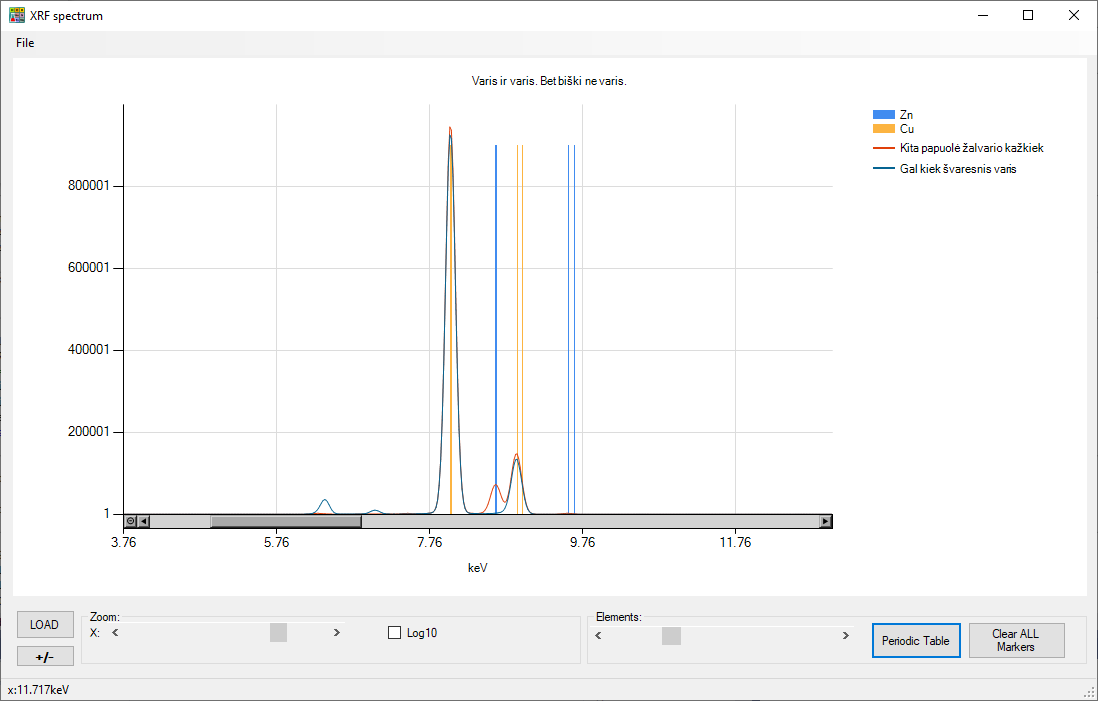
Two materials—one is copper, the other is also copper. But apparently, a little bit of zinc got in from somewhere. And this is what the PDF file with the same report looks like: copper-non-copper.
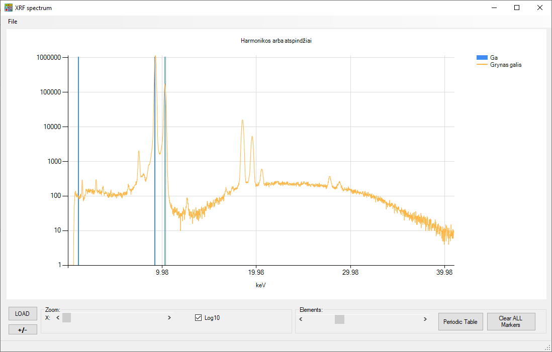
And here is an illustration explaining why sometimes XRF shows nonsense:
This is pure, 100% gallium measured. Its XRF spectrum is marked with a marker. And what are these recurring nonsense on the right? A new unknown element. Nobel Prize! Unfortunately, these are just harmonics when analyzing a strong signal. And now let’s think about how complex the software that does quantitative analysis must be: it has to consider harmonics, the fact that some elements cover others, that the X-ray tube itself is made of some metals, that there is also “scatter” radiation, when X-rays of any level reflect and fool the detector, that some elements absorb X-rays, while some materials let primary rays penetrate deeper and then fully lock any reflections inside, but when a weaker radiation is released, everything works.
This was a bit about my current job, not really related to electronics, right? 🙂
The program itself and some demo CSV files (already prepared for work): XRF.
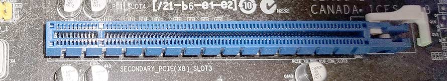
I have already written that I use many small disks. Together with the remaining large disks, it totals 10 disks. And I have always wanted to use some fancy RAID controller. However, no matter how many controllers I put into the spare PCIe (x8) slot, none of them worked, the computer didn’t even start BIOS
It’s a physical x16 slot, but it only has x8 lanes electrically. This is common in household computers – the first long slot is for the video card, x16, and the second is only x8.
The x8 isn’t a problem, as RAID, SAS, and SATA controllers were all x4 or x8. But all of them refused to work. Although, the second video card (x16) or even a dual network card (Intel® 82571EB 2x1Gb, x4) worked perfectly in this slot… The video card reported that it was working on x8. I didn’t ask the network card.
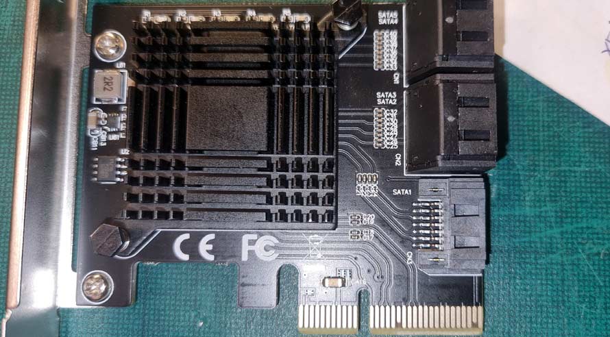
Even taking something as simple as a JMicron Technology Corp. JMB585 and plugging it into that slot, the computer doesn’t start. What’s the issue?
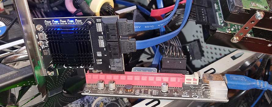
Although mechanically it’s an x4 slot, electrically it’s only x2. I haven’t seen x2 PCIe slots. Reading the chip’s datasheet, I came across the line ‘Supports up to two lanes of PCI Express’, which means it doesn’t necessarily have to be x2, x1 is also fine. My computer’s x1 slot doesn’t physically accept longer cards (and the ID line on this card isn’t connected to x1), but trying to connect through a PCIe riser, everything magically works:
Indeed, the other end is plugged into a free x1 slot.
Now the question. Why don’t the directly connected cards work? Too few free PCIe lanes? Misconnected ID lines on the cards or the motherboard? What’s the issue? And will this SATA-PCIe ‘bridge’ work if I mechanically cut the PCIe slot and connect the ID contact?
If anyone comments that the disk speed will be very low, my answer is – I know, those disks are only used for background backup copying.
2024 EDIT. All the problems were from shitty mainboard. Using new, i7-14K based system everything is OK. Simple, the system was to old for my experiments.
It all starts with a small nonsense: I decided to put a USB port logo on a 3D printed product. I couldn’t quickly find any STL file (for free or download without registration). So I thought to myself—well, there’s an SVG illustration, it’s a pure vector, I just need to “extrude” it upwards and everything will be great.
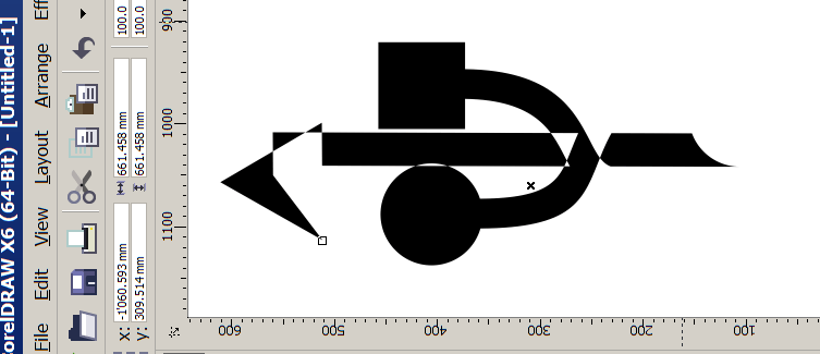
And then it started… My 3D printing and modeling program doesn’t accept such files. Well, it’s imperfect and not intended for that. The online converter also didn’t work:
We see how it cut off a piece from the square.
This requires something more serious: CorelDRAW, AutoCAD… I’m more familiar with Corel, so I open that SVG in Corel What a mess! Firefox or some Chrome handles the file perfectly! You can try it yourself.
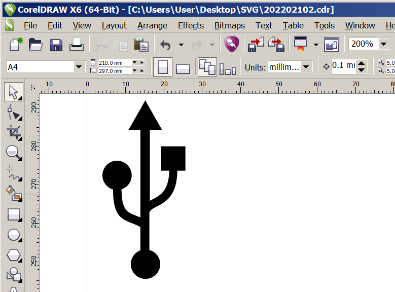
Well, the SVG file is essentially a text file with various graphic commands crammed into XML. With Notepad, I edited the file a bit and got a slightly corrected version of the SVG
Now the image is correct (I removed the white background along the way).
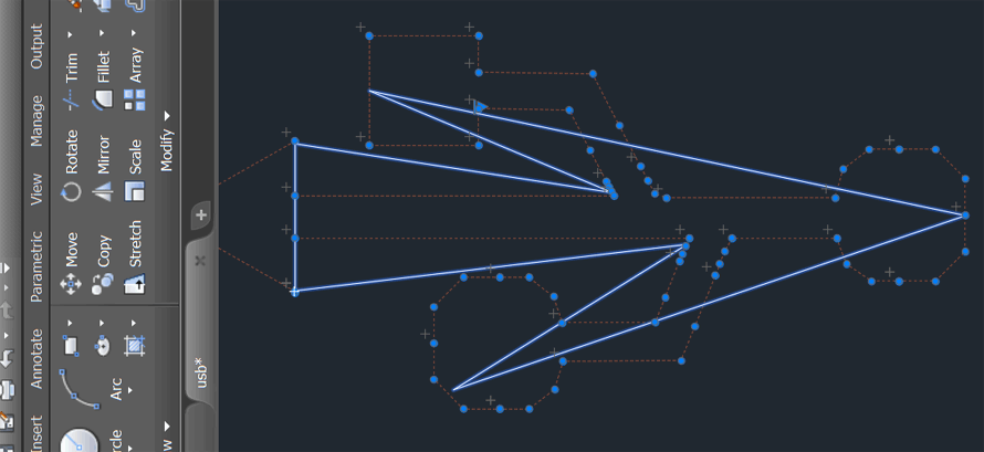
We export it to DWG/DFX, open AutoCAD to make it 3D and get frustrated:
What the hell? Why so few points? Where are the curves?
And then the “horses” started running away with me (“Меня понесло”). I completely forgot the initial task and decided to write the converter myself… First, I decided to understand how the pure unpacked SVG works, i.e., I decided to write an SVG language interpreter. Although they say the file format was created by W3C around 1999, I feel that its foundations come from the 1960s, when some pioneer, like HP or Xerox, was creating mathematical models for vector description.
Thus, a new project was born that no one needed. However, it was a very serious exercise for the brain:
The program is divided into several parts:
Windows printing/drawing/control
Text file preprocessor – the program removes all abbreviations, compressions (e.g., not writing zero) and converts it into “canonical form.”
SVG language interpreter – the program takes one command, collects parameters, calculates coordinates.
Geometry and trigonometry module which calculates and draws graphics. (this module is partly from the internet, there is a URL source code)
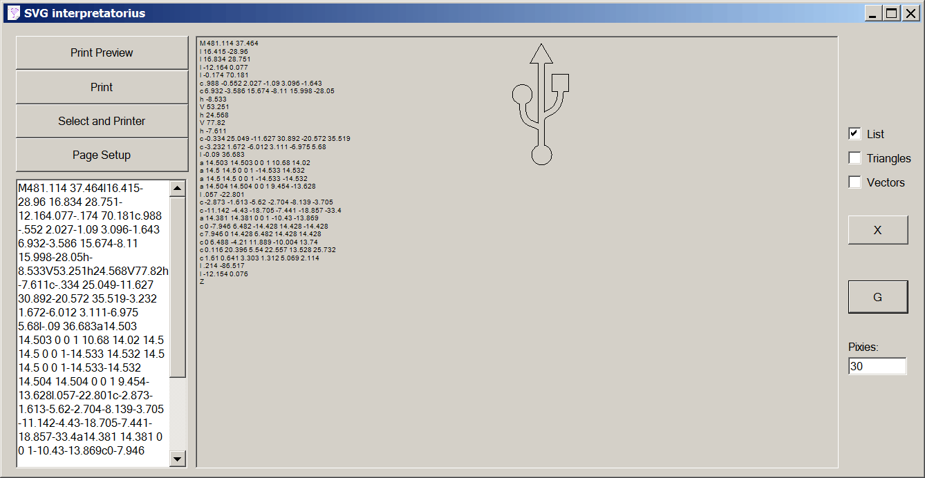
The program can print the result to a printer or pdf. That list next to the picture is the preprocessor-interpreted initial code:
I extracted this code from the initial SVG file. The same one that Corel couldn’t read… By the way, my software tries to interpret all commands. Unfortunately, there wasn’t time to debug everything. For example, I don’t know the difference between a “quadratic Bézier” curve and a “smooth quadratic Bézier” curve.
So I wrote cooler code than the Corel Draw programmers…
How do you like Levo’s mental exercise? There will be no continuation because my quasi-Covid ended and I will have to go to work again and there will be no time to play. This project took 3 evenings, including writing this article.
P.S. The initial SVG is not optimal. I could manually write a shorter (fewer commands) and the image would be the same. And who needs such “precise” numbers?
P.S.2 My preprocessed SVG interpreter worked perfectly with the online SVG2STL converter: USB LOGO STL. As the initial result was achieved. Whether it’s worth converting to STL or AMF, I don’t know anymore. 🙂
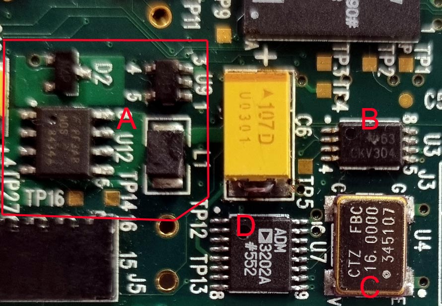
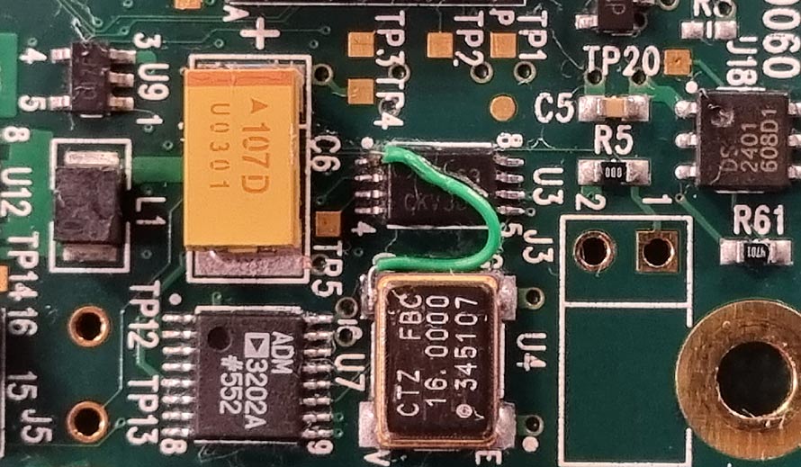
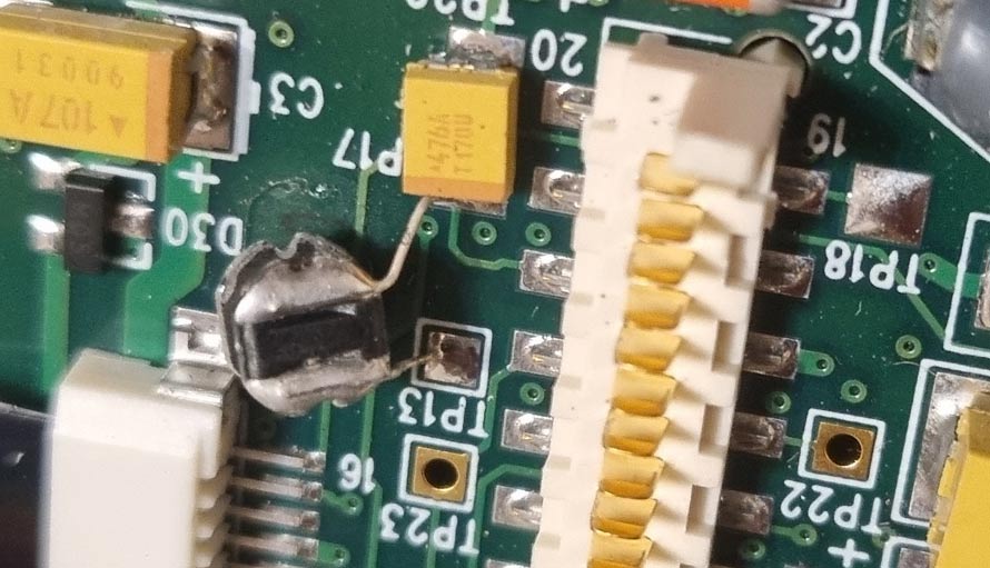
Continuing while still feeling under the weather (symptoms suggest COVID, but PCR says no), I took another look at the old XRF. I have already somewhat explained how it works and mentioned that the “black fin” isn’t trying to read the firmware from the SPI ROM. However, the oscillator is outputting its 16MHz. Let’s start examining the schematic:
A-part: This is the MCU core voltage regulator. Seems to be 1.2V. It works. Generation is visible on the MOSFET, and the voltage on the large tantalum capacitor is normal.
C-part: The 16MHz oscillator works.
D-part: RS232 converter. Signals pass through in at least one direction.
B-part: What is this? It’s a CDCV304 200-MHz General-Purpose Clock Buffer. It’s unclear why it’s here. The first pin is static, meaning the outputs will be empty.
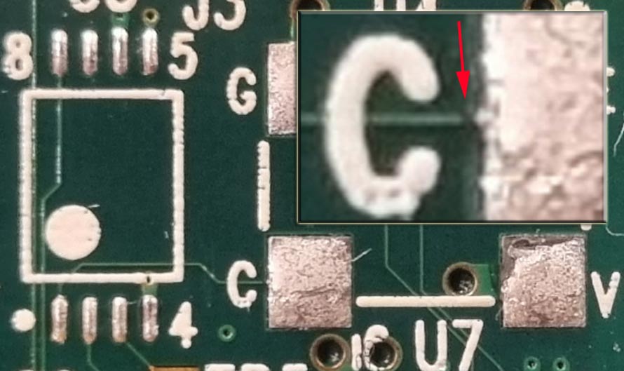
Let’s remove some components as traces run underneath them:
We see that the trace from the oscillator’s pin (out) goes directly to the buffer’s first pin (in). However, the signal doesn’t pass through. The contacts are fully isolated. Upon zooming in, it’s clear that there’s no trace at the “C” contact. Now, a rant and question: if PCB technology allows for thin traces, it doesn’t mean those traces need to be so thin. The oscillator is quite massive, the device is handheld, there might be thermal expansions involved… And there’s definitely plenty of space. I clearly remember that this type of failure (where the connection between the handheld and the device was lost) occurred in several devices of that generation. They repaired it by replacing the “motherboard” at the factory…
My hands are a bit shaky:
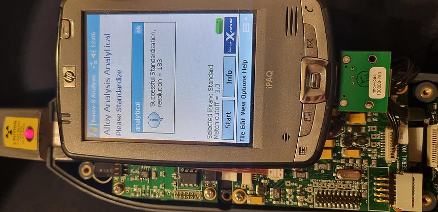
We connect the necessary contacts with Mylar wire and suddenly, data flows from the SPI chip and dynamic signals appear at the test points.
Even partially connected, everything magically starts working and the device calibrates (standardization). Now the problem is to gather all the case elements and screws since I scattered them on the table and around the room, not really believing the repair would be completed. And I also need to find a new battery for the handheld, as the current one (already rebuilt once) no longer holds a charge at all.
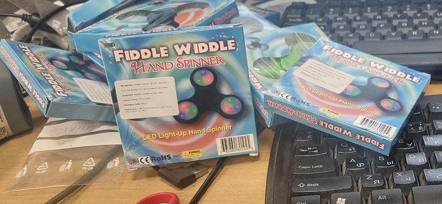
I’ve caught a bit of a cold (probably not Omicron), so I’m as angry as a hornet. Everything irritates me quickly. To vent my anger, I’ll rant a bit. I’m fed up with humanities people – ecologists. I can’t stand them. Let’s save nature, ban plastic straws. Not make plastic “biodegradable” like various plastic bags, but ban it altogether. And at the same time, a few years ago, all the humanities people said how great a thing the spinner is, how it helps autistic children (and hipsters)… By the way, on Friday, I showed a spinner to a young aunt, and she didn’t understand what it was… So let’s look at a specific model:
It supposedly helps with something, a super tool and so on. Now let’s look deeper. First, the packaging – good, it’s paper. It can be recycled or burned. The body – plastic. It can be melted down into flower pots or speed bumps.
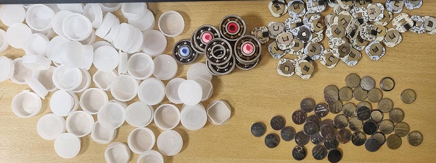
And this:
This spinner once glowed with colorful LEDs… Each spinner has one bearing (iron can be recycled) and THREE! PCBs with batteries.
Yes, take those batteries and shove them up some ecologist’s ass.
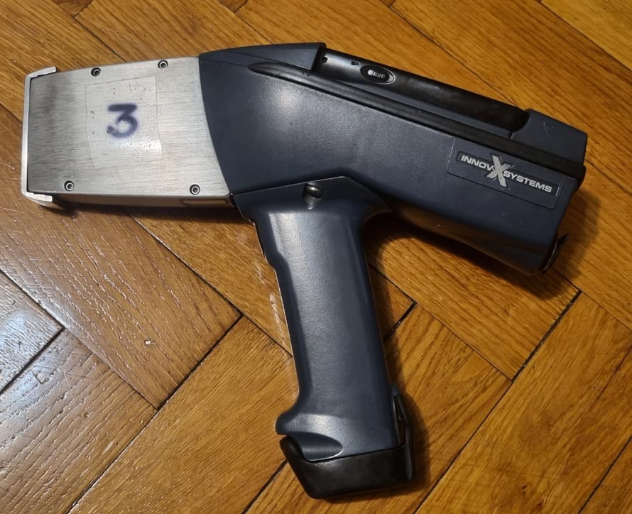
Unfortunately, January was completely empty. A bit of fiddling here, a bit of fiddling there. Some FPGA experiments with soft processors, some uninteresting repairs, some computers, and some programming. Nothing that could really interest readers. Maybe this unfinished repair will be a bit more interesting:
Innov-x alpha a-2000 There is this old device, a handheld X-ray fluorescence spectrometer. It is one of the oldest models – Innov-X systems inc, alpha-2000A (α-2000). From the times when this company existed. Now it’s a part of Olympus. Back then, the device cost a fortune, though, to be honest, new XRFs also cost quite a lot. The principle of operation is that a weak X-ray beam reflects off the material being analyzed. These soft X-rays are detected and their energy measured. From there, it’s purely statistics based on KeV…
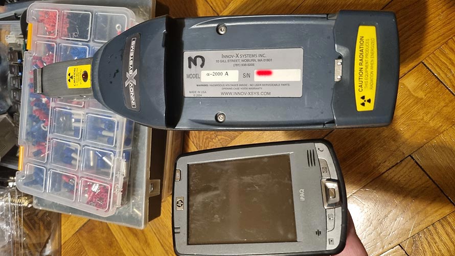
Innov-x alpha a-2000 All calculations are done on an HP handheld. Since each detector is unique, without the appropriate calibration software, these devices don’t show anything useful. And this particular device does not communicate with the handheld.
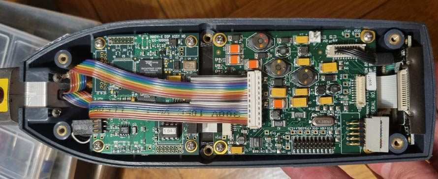
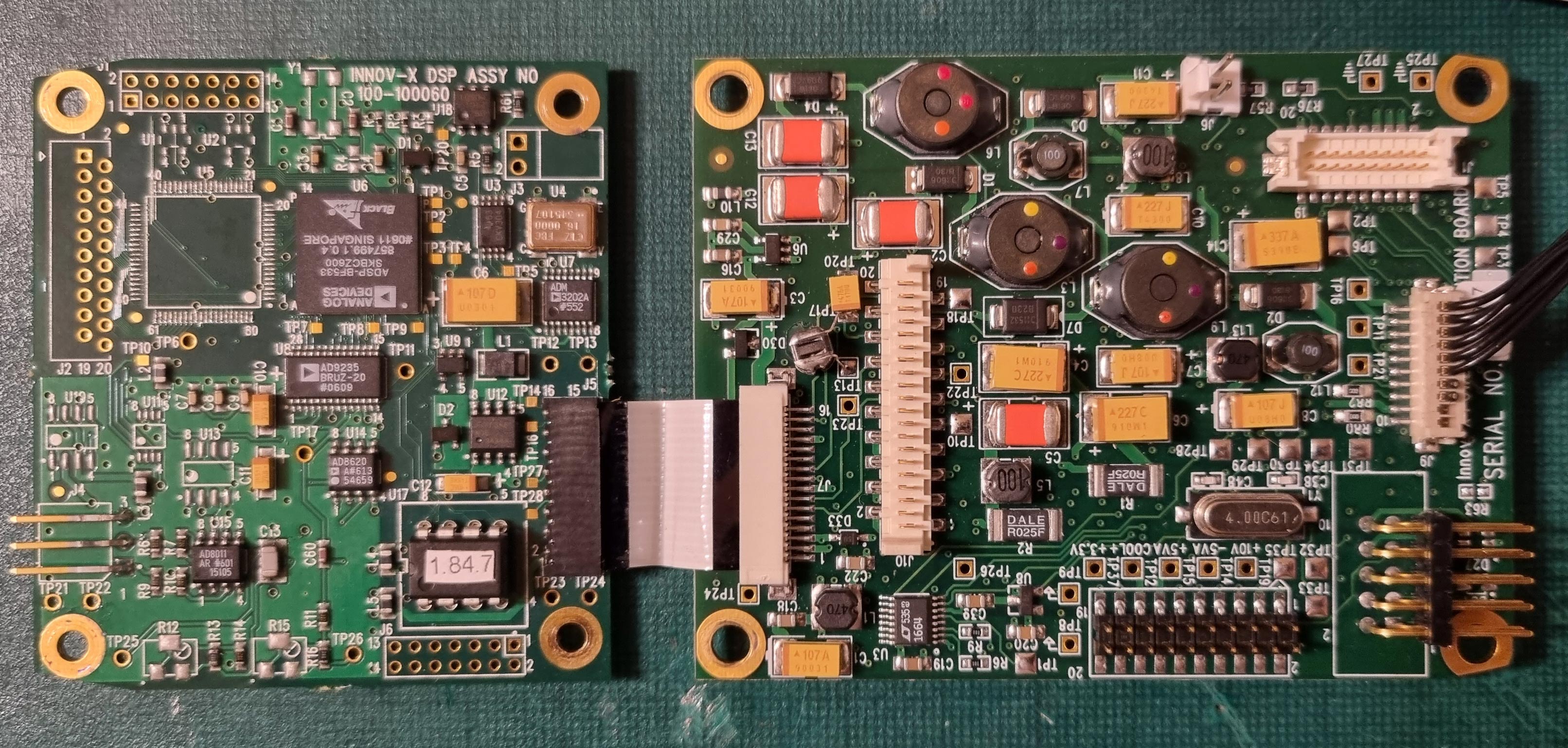
Innov-x alpha a-2000 Inside, it’s pure old-school. Two boards – power supply, temperature stabilization. And some DSP or CPU that probably collects the initial spectral data. All communication between the DSP/MCU and the handheld occurs via RS232.
There are unexpected solutions on the board 🙂
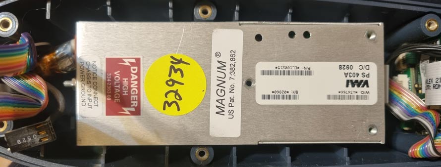
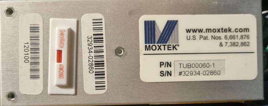
Here is the high-voltage source for the X-ray tube.
I don’t know the exact parameters of this model, but new XRFs can have up to 50kV and 0.2mA. That’s a maximum of 10W of electrical X-ray power… It’s evident that the device experienced over 50G, as indicated by the red marker. Maybe it’s a bit incorrect to call it a power supply since it’s an unserviceable module called a “Moxtek Analog X-ray Source,” not visible in my photo, but a small X-ray tube is connected to this box. It’s better seen on the manufacturer’s website. The number of this module aroused my curiosity – if the analogy holds, it’s a 60kV X-ray module.
The signal from the handheld goes to the right PCB and the right side of the PCB (TP11, TP21), then goes to the flat cable, on the other board it’s TP27, TP28 and goes to the ADM3202A chip. On the TP contacts, one of the RS232 signals is visible, the other is completely dead. Either the DSP or CPU is dead, then the device is thrown away, or the RS232 signal shaper is dead. Which is more logical since it has contact with the outside and something might have shorted there. So it lies on the table… By the way, I have another alpha that works, just shows inaccurate readings… And one delta that works only when kept in the fridge – the detector’s Peltier cooler is not working well anymore. None of these devices are repairable at the factory anymore, now they only make Vantos… These are left for experiments, unfortunately, they cannot be sold – Lithuanian laws do not allow it.
If you happen to be involved in USB device design and frequently connect unsuccessful experiments, Windows secretly accumulates unnecessary information. Later, when connecting a “Generic” printer, there’s an issue – it’s unclear which port works:
Ghosts Only one of them is real. All the others are remnants from improperly programmed devices. However, Windows itself somehow does not allow these ports to be removed. Other ports can be removed, but these are blocked.
Even if you mark to show “hidden” devices in “Device Manager,” so many ports are not visible.
But there’s a trick:
Ghosts Here, an additional system variable is recorded. Then “Device Manager” starts showing all the “ghosts.” The variable is called “devmgr_show_nonpresent_devices.”
Ghosts The picture is rotated because it turns out too long.
Now you can gradually start uninstalling them. Unfortunately, you can’t delete them in bulk.


