
(AI translated)
Continuing while still feeling under the weather (symptoms suggest COVID, but PCR says no), I took another look at the old XRF. I have already somewhat explained how it works and mentioned that the “black fin” isn’t trying to read the firmware from the SPI ROM. However, the oscillator is outputting its 16MHz. Let’s start examining the schematic:
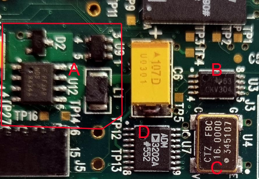
- A-part: This is the MCU core voltage regulator. Seems to be 1.2V. It works. Generation is visible on the MOSFET, and the voltage on the large tantalum capacitor is normal.
- C-part: The 16MHz oscillator works.
- D-part: RS232 converter. Signals pass through in at least one direction.
- B-part: What is this? It’s a CDCV304 200-MHz General-Purpose Clock Buffer. It’s unclear why it’s here. The first pin is static, meaning the outputs will be empty.
Let’s remove some components as traces run underneath them:
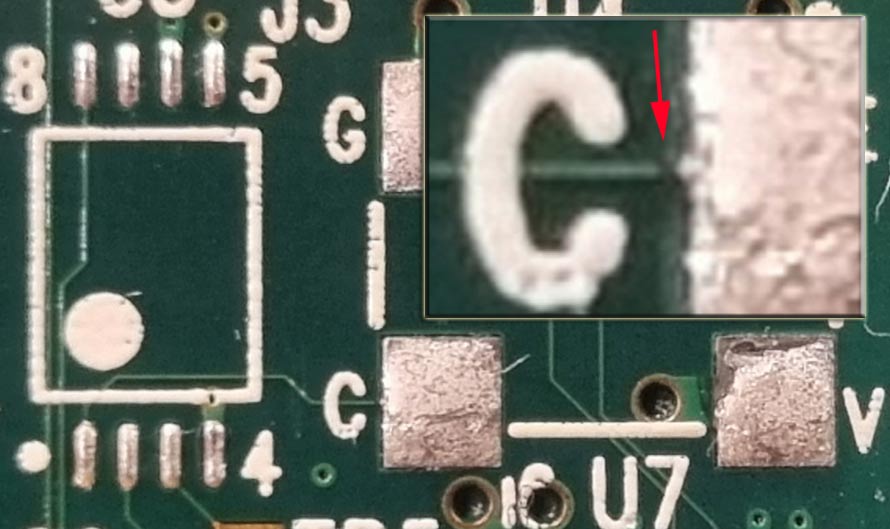
We see that the trace from the oscillator’s pin (out) goes directly to the buffer’s first pin (in). However, the signal doesn’t pass through. The contacts are fully isolated. Upon zooming in, it’s clear that there’s no trace at the “C” contact. Now, a rant and question: if PCB technology allows for thin traces, it doesn’t mean those traces need to be so thin. The oscillator is quite massive, the device is handheld, there might be thermal expansions involved… And there’s definitely plenty of space. I clearly remember that this type of failure (where the connection between the handheld and the device was lost) occurred in several devices of that generation. They repaired it by replacing the “motherboard” at the factory…
My hands are a bit shaky:
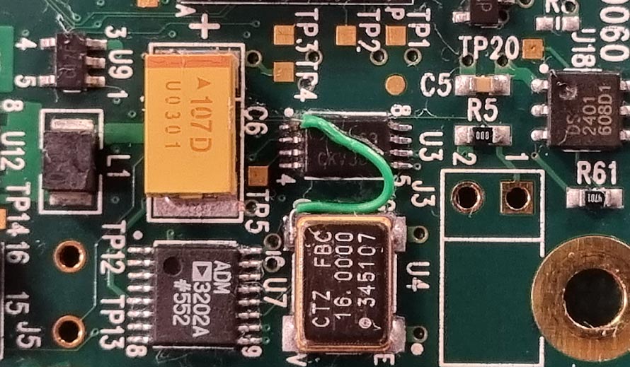
We connect the necessary contacts with Mylar wire and suddenly, data flows from the SPI chip and dynamic signals appear at the test points.
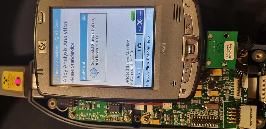
Even partially connected, everything magically starts working and the device calibrates (standardization). Now the problem is to gather all the case elements and screws since I scattered them on the table and around the room, not really believing the repair would be completed. And I also need to find a new battery for the handheld, as the current one (already rebuilt once) no longer holds a charge at all.