
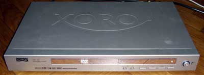
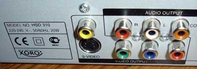
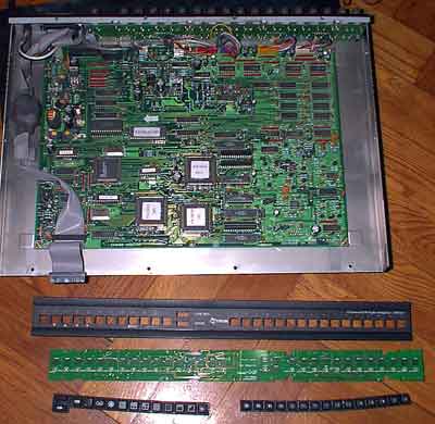
Let’s look inside Xoro DVD/DivX/Xvid player. I received few HSD 310 for disassembling. HSD 310 is lite version of HSD 415- only additional audio and video outputs installed and 5.1 sound support.
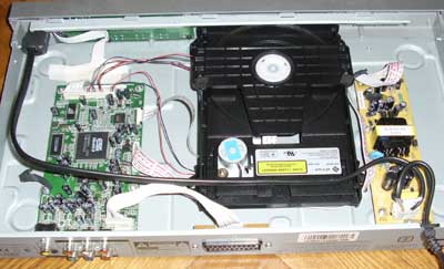
There are less components than in Vido DVD player. Power supply is made from less components and with smaller PCB. I didn’t find any EMI protection inside the PSU, only one capacitor- I think it is mandatory to pass device to EU market. 🙂 So this device may generate lots of noise to power lines and it may be prone to various interferences from power line.
PSU is made using “green psu” chip DL0165 (Fairchild FSDL0165RN). Max power of this chip is about 13…23W depending on cooling situation. This type of PSU didn’t require to cut off main when not in use, but engineers installed hardware power switch in the front of the player. So you don’t need to pull out power cord when you leave your home for vacation, just press power switch.
The DVD player itself is Chinese brand made- some “Shima industries” product. I can’t tell about the quality of reading. I tested only discarded players. One player is playing almost all my DVDR and CDR disks without any problem. Other device refused to play original audio CD, while playing CDR media without any problems. One device was with small hardware problem- disk fixing unit was unbalanced. I placed washers to their proper places and device is working fine.
The heart of the device is standard ESS Vibrato II CPU/DSP (ES6688FA). I downloaded new firmware from manufacturer’s site and flashed to the player. Just for fun and testing. The flash procedure is very simple- just record new flash file to CD, insert to the player and wait. The more advanced HSD415 mainboard is identical, only all components placed compared to 310 mainboard.
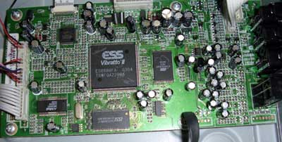
HSD-310 is lite version. This means, that it lacks of component, D-sub (VGA style) RGB output, optical and 5.1 sound output. I connected Trustmaster LCD monitor to RGB output of the DVD player and it work fine. As I have HSD-415 mainboard, maybe in the future I’ll test various combinations of firmware and hardware.
