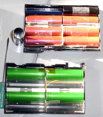
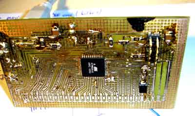
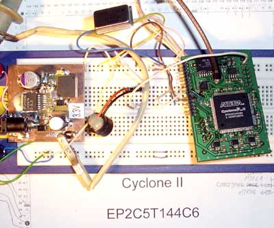
As the flex was killed, I needed to test the Cyclone chip. But I need good 3.3V power supply for it. The core and PLL voltages are lower, but linear regulators were already placed on the PCB. The only good 3.3 source was computer power supply (ATX model), but it is too big, too noisy to be placed on my desktop. I was lucky and in trash pile with cyclones I found other PCBs- some with switched 3.3 (and other voltages) regulators and quite many Atmel ATMEGA16 MCUs. (Thanks for support!) More than dozen free ATMEGA will force me to use them :).
So, I have quite big stock of LM2676S-3.3 chips. It is:
The LM2676 series of regulators are monolithic integrated circuits which provide all of the active functions for a step-down (buck) switching regulator capable of driving up to 3A loads with excellent line and load regulation characteristics. High efficiency (>90%) is obtained through the use of a low ON-resistance DMOS power switch. The series consists of fixed output voltages of 3.3V, 5V and 12V and an adjustable output version.
The SIMPLE SWITCHER concept provides for a complete design using a minimum number of external components. A high fixed frequency oscillator (260KHz) allows the use of physically smaller sized components. A family of standard inductors for use with the LM2676 are available from several manufacturers to greatly simplify the design process.
The LM2676 series also has built in thermal shutdown, current limiting and an ON/OFF control input that can power down the regulator to a low 50µA quiescent current standby condition. The output voltage is guaranteed to a ±2% tolerance. The clock frequency is controlled to within a ±11% tolerance.
BTW, using external voltage divider can help us to change output voltage.
D2 – just powerful diode protecting device from reverse polarity. Sometimes I connect untested wall adapters and some of them are AC/AC type… Typically from old external modems. I have already damaged one ethernet switch with such adapter.
C1 and C2 are line voltage filters and energy storage devices. The capacitance is not very important thing, place as much as you think. But try to use low ESR capacitors. C3 and C5 is energy storage devices. Low ESR is mandatory here. Capacity- 1000µF or more. C4- boost capacitor, read data-sheet for more details, 0.01µF at 50V. D1 is fast, schottky diode. Voltage dropout less than 1V. The coil is selected from table in datasheet. Don’t worry about exact value. This only lowers the efficiency of the regulator a bit. I used 27µH coil. R2 and LED2 is just to show that something is working. The chip pin 7 is left floating. It can be used to switch off the regulator.
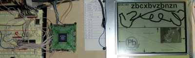
Everything is placed on small PCB with pins for connection to breadboard. Do not build switched power regulators using “wire” connections or breadboard. High frequency and current with long wires will cause strange effects.