 There are lots of rumours in the internet about high power DVD lasers and about hacking them. I decided to test some of the rumours. Theoretically, there are two lasers in modern DVD recording device. Power of the laser must be strong enough to change the physical properties of recordable media. In this post, I didn’t examine IR (infra red) laser used in same device for CD/CDRW media. I tested RED laser used in DVD recording and reading. The newer DVDRW device, the faster recording speed- the more power in laser.
Laser diodes is CD/DVD drive come with various optical lenses. These optics is not very useful for burning experiments- the laser beam is separated and then focused in very short beam. And for real “laser gun” we need long range optics. There two types of laser diode modules- stand alone lasers and lasers with multiple photo-diodes (detectors) in same package. Older laser diodes were built with photo diode build in package. This diode is used to detect laser generation and to measure optical power. In some new devices this diode is missing. Even if the package have three pins, I didn’t find photo diode inside, even when I disassembled diode.
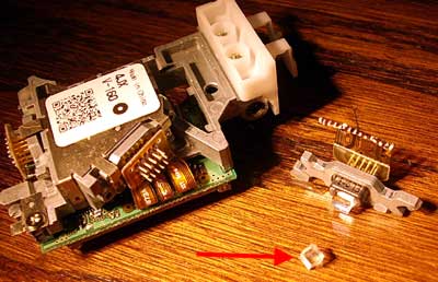
Laser diodes are sensitive devices. Especially they are sensitive to static discharges and over voltage-over current modes. I damaged 4 diodes experimenting with my power supply- the transitive process during power-up and power-down killed them. On some laser diodes there is optical element glued to package. It is beam splitter- you can get remarkable interference lines when using these splitters, but for power experiments we need to remove it. After removing, the “can” is open to free air (and some diodes are made without protection), so keep “open” diodes dry.
Laser diodes, same as LED diode is current, not voltage user. But using simple ballast resistor is not good way to solve the problem. The PSU for laser diode is current regulator with dual feedback: one from current, another from photo diode. And PSU with over voltage protection. The PSU is very simple (I’ll post two version of PSU I build). The components are very cheap and everything can be found in old computer motherboard.
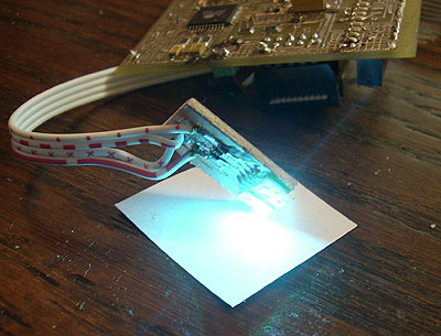
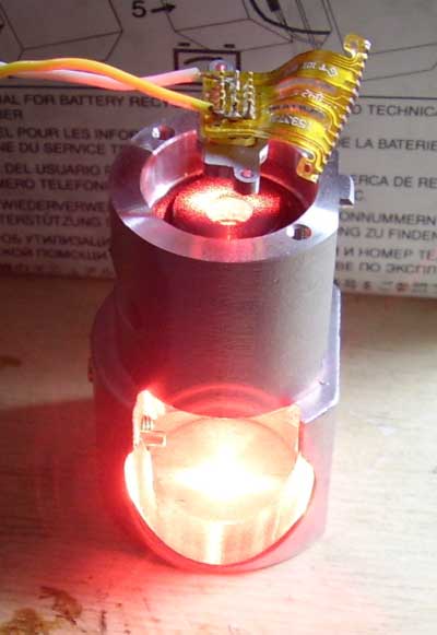
Here is the image of working DVD recording laser diode without collimator optics. Other, simple diode without heat sing is seen too. Never use high power laser diodes without heat-sink. The current in threw this diode is about 150mA and according to the datasheet, the optical power is about 100mW.
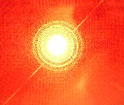
If I place diode to my digital camera lenses I see such nice image. The light is dissipated, so there is no possible damage to camera detector.
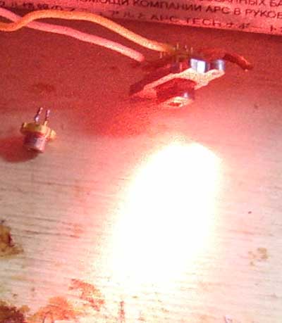
Here is first experiments trying to focus laser beam. I used optical collimator some some old IR laser. This collimator is not very suitable to high power RED lasers. There is big problem to get good collimator for such laser.
And now some words about safety. Lasers used in DVD-R device and working in full power are potentially dangerous devices. So: NEVER STARE TO LASER BEAM WITH REMAINING EYE! IR (infrared) laser are double dangerous- they are powerful and invisible.
I found datasheet for Rohm laser diode RLD65PZB5: max optical power (pulsed, 50% duty cycle) is 240mW! Current according datasheet is about 400mA.