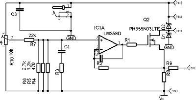
This is first version of laser diode power supply. I borrowed circuit from die4laser.com and changed it a bit. It is classic current source using n-channel power device. It is better to use p-channel devices here, but now I have only n-channel mosfets on my workbench. They are cheap and easy to get. Modern mosfets a very compact and powerful devices. Now they are very steady devices and even can work in very high temperature. During experiments I overloaded supply and transistor self-melted solder (I am using lead solder)- working temperature of particular device is 150oC!

Resistors R4, 5, 6- they are used to set max current. R8- is shunt. If we place here 1 ohm resistor, we get 1V reading for every ampere. R2, 9 -1k. R1 is about 600 ohms. R3, C1- is soft start circuit. Not implemented in current design. C2- only few hundreds of picofarads. Only to prevent from auto-generation. C3- is a bigger one. Transistor- any n-channel mosfet powerful enough to carry working currents and voltages.

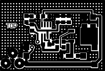
This is PCB image. If this picture is printed with 200dpi resolution, it can be used to build PCB.
This WAS prototype of power supply. It killed few laser diodes. So I made another version and I place circuit diagram in next blog entry when I’ll translate it from Lithuanian version. I recommend to use regulated power supply and not more than 5V.
