There are lots of “rainbow LED” projects in the internet. So, I decided to place something similar in my weblog.
There are 4 hardware PWM outputs in ATMEGA16. So do not need to build fancy software routines to make pulse width modulation (PWM) by software. Just define PWM output in the chip and forget. Other chips may have less of more PWM outputs. Just check the data sheet.
I am using 3 color (tricolor) LED form some cheap flatbed scanner. This LED module is very good because it is small, all LEDs are placed on same chip. Also it is very easy to solder it. Also, I guess, that light power of LEDs are compensated and equal to current. I think that if I pass same currents in all three diodes I’ll get white color, no need to adjust tint (hue) of the output.

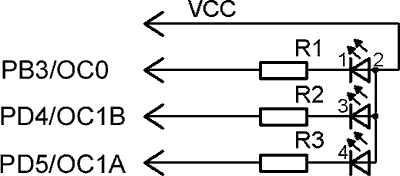
Circuit diagram is very simple- diode module, three 470 ohm ballast resistors. Everything is connected to my experimental PCB. OC0 is connected to “firmware” connector, OC1A, OC1B and Vcc can be found on LCD connector.

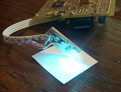
Here is the image of working device. Sorry for the quality, my digital camera is not making good images of bright light sources (diodes from scanner are very bright, they are used to light whole scanned line).
Here is short move made by same digital photo camera. Sorry, but the colors are ugly. In real world is full rainbow on your desktop.
Firmware is very simple. It is using “0” timer as interrupt source and also it is the clock for zero PWM channel. So I can’t make timer 0 very slow- with lower frequencies the LED is flickering. So I placed extra calculations in interrupt routine to slow down main color cycle. Other two diodes are connected to timer 1 output.
All the math is made in two procedures. They calculate “H” (hue) value calculations to RGB output values. My H2RGB procedure is identical to MS paint color palette picker (with fixed other values).
Source code: 20071101.zip.

labai ydomus straipsnis. :)) perskaiciau kelis kartus. 😉