HiFi Stereo Tube Amp Schematics

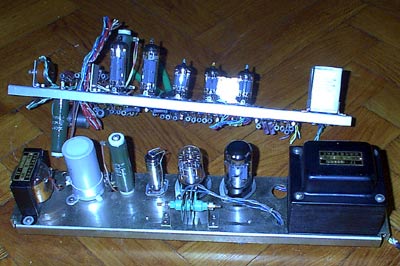
In older post I wrote about unified soviet tube audio amplifier. This is from “high class” device. Today, I found the schematics of “highest class”, the HiFi audio device: AM/FM radio, record player. The output is 6W of pure tube power with lowest distortion. This device was manufactured in 1964 and schematics published in popular radio magazine in 1965. With some our days modifications it is possible to build quite cool power amp with quite popular tubes.

HiFi stereo tube amp schematics
The circuit diagram of audio amp for printing

HiFi stereo tube amp schematics
The circuit diagram of power supply for printing

Transformer description
Number Winding count Wire thickness Core
TR1, TR2
3-4 1000 ПЭЛ 0.14 Ш20
4-5 300 ПЭЛ 0.14
5-6 300 ПЭЛ 0.14
6-7 1000 ПЭЛ 0.14
9-1 82 ПЭЛ 0.69
     
TR1 POWER (PSU UNIT)
1a-3a 0-458-530 ПЭЛ 0.64 TC-135
1b-3b 0-458-530 ПЭЛ 0.64
5a-5b 505x2 ПЭЛ 0.41
7a-7b 29x2 ПЭЛ 1.20
9a-10a 14 ПЭЛ 0.90
9b-10b 14 ПЭЛ 0.90
11a-14a 0-30-60-100 ПЭЛ 0.31
DR1
н-о-к 0-2890-2950 ПЭЛ 0.16 Ш16x16, >3.5H

Tube data:
Л1, Л2, Л3: 6Н2П, ECC83, 12AX7 (but with heater modification)
Л4, Л5, Л6, Л7: 6П14П, EL84, 6BQ5, 7189A

Posted in Anything | 2 Comments

Camera flash circuit

Here is the guts of disposable camera.

Blicas

Blicas

flash circuit
Simplified schematics diagram of camera flash.

Blicas
Some high power flash tube from scientific equipment.

Simple few transistors generator and transformer A transforms 1.5V battery voltage to few hundred of volts. This is quite high voltage. Then this high-voltage current passes through a diode, which rectifies current to DC. This DC current is stored in quite big capacitor.

The capacitor is connected to the two electrodes on the flash tube at all times, but unless the xenon gas is ionized, the tube can’t conduct the current, so the capacitor can’t discharge and tube didn’t flash.

The capacitor is also connected to a small gas discharge tube via a resistor. When the voltage in the capacitor is high enough, the small tube lights up. This acts as an indicator light, telling you when the flash is ready for action.

When you press trigger of camera, the trigger closes briefly, connecting the capacitor to a second transformer. This transformer boosts the 290-volt current from the storage capacitor up to between 1,000 and 10,000 volts, and passes the high-voltage current pulse onto the metal plate next to the flash tube. The momentary high voltage on the metal plate provides the necessary energy to ionize the xenon gas, making the gas conductive. And the flash tube discharge.

Full schematics I found in the internet

Posted in Anything | 3 Comments

HDD Grinder Stone

In some www I found image of HDD transformed to grinding stone. It was placed in “jokes” category. But I decided, that small grinding machine is useful for hobbyist. I use old 2G HDD “Western Digital Caviar 22500”. It is only 5K rev/minute HDD. Removed cover and all heads, magnets. Took sandpaper and glued to one disk plate.

Grinding machine
Grinding in action!

The engine is quite weak, but this “grinding machine” is usable. Next version will be mad from some quicker drive. I am looking for 7K SCSI Barracuda… Or maybe, if I’ll find, it will be some very old, but powerful, multiplate server hdd.

Posted in Anything | Leave a comment

Typical Tube Amp used in Soviet HiFi :)

Soviet radio devices used typical schematics for same class. They called it “unified chassis” or “unified frame”. Here is part of the schematics from II class radio+phone player. Power output, according to manual, is only 1.5W, but it played very loud!

Typical audio amp in Russia at 1966
Big Circuit diagram for printing.

Pin 17, line 5: +200V
Pin 15, line 3: +260V
Pin 21, line 1: +280V
Pin 20, line 2: +280V
Pin12: Audio in
R1: volume
R2: treble
R3: bass
L1, Л1: 6Н2П, ECC83, 12AX7 (but with heater modification)
L2, Л2: 6П14П, EL84, 6BQ5, 7189A

Power supply for this tube amp.
Tube Amp PSU
Big Circuit diagram for printing.

Posted in Anything | 2 Comments

Ferrite Core Memory

For recycle, we received some “Medical computer” and inside I found this nice thing. The DIMM nearby is to compare the sizes.

Ferrite Core Memory

A small ring, or core, of ferrite (a ferromagnetic ceramic) can be magnetized in either of two opposite directions (clockwise or counterclockwise). Therefore such a core can be used for storing a bit of information. For almost 15 years, ‘core’ has been the most important memory device. The invention of core memory in 1949 was a leap forward in cost-effectiveness and reliability. This device is dated in 1966. This memory “module” is made in Japan. I think by TDK. It consist of 5 PCBs with 4 “mats”. Total 8000 bits of RAM. It is whole 1000 Bytes (0.9765625 kBytes)! Cool.

Core memory has been in use until recently for special purposes, because it retains the information when the power is switched off, and it is resistant against radiation.

Ferrite Core Memory

The physical basis of core memory is the fact that a current sent along a wire passing through a ferrite core sets a persisting core magnetization, if the current exceeds a certain threshold. A current in the opposite direction will reverse the direction of the magnetization. In this event a voltage pulse will be induced in another wire threaded through the core, the ‘sense wire’; the polarity of this pulse is determined by the original magnetization direction. Clearly reading is a destructive operation, and as part of the read cycle the original state of each core must be restored.
Core memories were often organized as a planar matrix, the ‘write’ wire being split up into two wires (row, column) each carrying half of the threshold switching current. This made it possible to address a specific core in the matrix for reading or writing.

(Smart text is copied from internet.)

BTW, this device originated such known term as CORE DUMP. 🙂

Posted in Anything | Tagged | 1 Comment

Barretter

Resistor inserted into a circuit to compensate for current changes (as those arising from temperature fluctuations) [syn: ballast resistor]

Barretter
B-300-G by NEC and unknown Soviet made.

Tube filled with pure hydrogen and thing iron wire inside. When iron wire is cold, the resistance is low. When temperature rises, the resistance is bigger. The difference of cold and hot resistance is about 10 times. The current going threw berretter heats the iron wire. So the current in working range is stabilized. Used in older equipment. Sometimes in filament circuit in series to tube heaters. In modern time barretter can be replaced with PTC thermistor.

Posted in Anything | Tagged | 1 Comment

Tube Amp power supply

From “something I found”:

Some tubes

The nearer thing in the photo is power supply for some medical amplifier. The further one is the amplifier by itself.

The interesting part for tube audio amplifier lovers is power supply. It is stabilised +150V power supply. Also 6.3V for heater and something like 20V stablised on current. I’ve tested power supply and it is working fine. And it is made in 1966 in Japan.

Transformer used in power supply:

Input 220V.
Output: 20V @ 0.3A, 5V @ 2A (diode heater), 2x385V @90mA (with central tap), 6.3V @ 3A.

Tubes: 5AR4, B-300G, VR-150MT

Some choke- everything is written in Japanese.
Capacitors 2x20mkf @ 500V.
Other: selecnium rectifier in 20V line, few smaller caps and resistors.

Other board is populated with tubes: 2 x 6BQ5 ir 3 x 12AX7.

Posted in Anything | Leave a comment

Old tube amp

I found old audio tube amp:

Tube amp

Tube amp

As I can feel some damp in the amp, I can not tell if it is working. I put it in a warm and dry place for some time. The tubes inside are:

4 pcs. of EL34 (3 maybe made in Hungary, one is Siemens made)
ECC85 telefunken made
6Ж32П soviet made.
Capacitors are made in Hungary. It seams, that electronics was reapaired.

There are no inscriptions on the box. Only some trace like “LACK”…

Posted in Anything | Leave a comment

BidPay is dead

There was very good service from Western Union. This was very easy way to pay online for someone. It was working fine for few years, but today on their web site there is announcement:

“Effective December 31, 2005, BidPay.com, Inc. will be discontinuing operations. As a result, BidPay will no longer offer payment services to the online auction industry. We regret any inconvenience to our users and thank them for their loyal patronage. Customer service will remain available at bidpayservice@bidpay.com through the month of February. ”

As paypal is still not working in Lithuania I am stuck with bank cheques or postal money orders. And no any suitable online payment options for receiving money.

One of the last bank cheques

Posted in Anything | Leave a comment

UTP lightning protection schematics

First of all examine APC (American Power Conversion) LAN surge protector. It is removed from some APC UPS.

Surge suppressor

The circuit is very simple. Diodes D1-D4 and D6-D9 are IN4006. The D5 diode is more interesting. It is 1.5KE6.8CA. This is special diode: 1500 WATT PEAK POWER TRANSIENT VOLTAGE SUPPRESSOR.

APC surge protector circuit

Note J3. On PCB it is small gap between GND and signal wire.

In older telephone equipment special discharge devices are used for surge protection.

Surge suppressor

These devices are simple gas discharge tubes which can handle very high current for a short time. There single line protectors and protectors for symmetrical lines. We can use any of them in LAN protection.

LAN lightning protection schematics with gas discharge protectors

One note to schematics. One side of line is directly grounded. In some cases, cable grounding must be done using some discharge device. Especially if the cable can be grounded in both sides. This will stop residual current in the cable.

Note: Grounding must be real! It must be real earth connection.

Here you can see discharge in the bulb:
Burning discharger
BTW, high voltage generated by welder ignitor. P-27 gas discharger specifications: ignition voltage 310…390V, Resistance 5*103 Mega ohms, max pulse current 2000A, constant current 2A, max pulse width 50…60μs, max frequency of pulses 50Hz.

Silicon TRANSIENT VOLTAGE SUPPRESSOR, clamping unidirectional diodes
5KP58: 5000W Transient voltage suppressor, (58V, 400A)
1N5908: Unidirectional diode, peak pulse power 1500W (10/1000mks), reverse stand off voltage 5V. The 1N5908 and SM5908 are dedicated to the 5 V logic circuit protection (TTL and CMOS technologies). Their low clamping voltage at high current level guarantees excellent protection for sensitive components.
BR211-140: Breakover diodes. Breakover voltage 140V, pulse 40A. A range of bidirectional, breakover diodes in a two terminal envelope.Typical application is transient overvoltage protection in telecommunications equipment.

Posted in Anything | 30 Comments