Scanning for WiFi

In old times, when article was originally posted in 2008 wifi was not popular in our country. Now (2015), then article was translated, situation changed.

I aquired several old handheld computers for tests. So I started wifi scanning software and made a short trip arround.

wifi hardware

My trip is arround local university campus, so it was quite “high tech” rich one.
My moving speed was about 50km/h, so not all WiFi AP were scanned. Trip was about 7km long and I managed to find about 74 WiFi spots.
There are lots of WiFi networks with default names, and I think, that several ones were with default passwords too. Especially ones without encription.

WIFI scanning

In fact it is just “filler” article. So, keep calm, and wait for more informative articles, o just try to read Lithuanian articles.

Posted in Anything | Leave a comment

Old style TV transmitter

From time to time I have articles about teardown about some strange items. It is not regular home items, but something more exotic… It is either 10kW or 20kW TV transmitter. It from Lithuanian region Dūkštas, Ignalina. Device is made in 1993 in soviet union, and it is printed on it Дукштос, Сниечкус. Despite that it is made in 1993, the technology used in it is about 1965.

Main element in transmitter is tubes: Klystron and traveling-wave tube (лампа бегущей волны). But this article is photo story, so there is lots of pictures and only few words of text.

This not heating tube, but vacuum tube with magnets on it. This is so called traveling-wave tube, magnets keeps electron beam focused. These tubes were used for amplify output power.

Just info from wiki:

A traveling-wave tube (TWT) is a specialized vacuum tube that is used in electronics to amplify radio frequency (RF) signals in the microwave range. The TWT belongs to a category of “linear beam” tubes, such as the klystron, in which the radio wave is amplified by absorbing power from a beam of electrons as it passes down the tube.

Power tube TV transmitter
Continue reading

Posted in Anything | Leave a comment

RGB matrix: organization

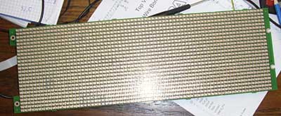
This post is about structure and organization of big RGB LED matrix. Just notes to remember how it works, as paper notes tends to be lost. And it is much easier to find information back in the internet compared to my paper notes.
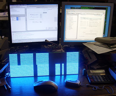
I completely debugged and reverse engineered the RGB matrix from previous posts. Now it is time to explore, how engineers from Adaptive Micro Systems LLC from Milwaukee, USA, designed it.
RGB matrix
Matrix is made from total 1728 LEDs placed on PCB in 24 rows and 72 locums. Total count 5184 discrete diodes. There are two parts (mega-rows) to access upper and lower parts of the matrix: LE_MBI_UPPER and LE_MBI_LOWER (pins 69 and 70 on Cyclone FPGA). One mega row is made from 12 regular LED rows. /LE signal pulse is used to move data from input buffer to output buffer of MBI5026CD chip. (See MBI5026CD datasheet).
All these 12 rows are controlled (via mosfet switches) by regular 74 series chip 74HC154. It is binary to 16 output decoder. Only lower 12 output are used. This chip is connected to FPGA: A0-A3 (HC154[3..0]) to Cyclone (pins 32, 33, 34, 35), OE2 (HC154OE) to FPGA pin 32. Meanwhile OE1 is connected in more complicated and interesting way. There is ingenious protection from system freeze (if matrix could be freezed due to system glitch, the LED may be burned)- there is some discrete parts, diodes, capacitors and resistors which combines to some sort of watch dog. If there is constant clock feed to watch dog (RC_UNKNOWN1, pin 37) the decoder is working. If there is static signal on pin, the decoder is switched off.
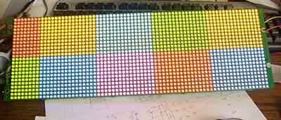
All the lines (except first two squares) have 16 RGB LEDs, all connected to three serial-parallel-LED-driver chips (MBI5026CD). Every chip is for one color only, because each color have it own working current. First squares (columns) are missing LED because the matrix is only 72 LED wide, meanwhile “logically” is bigger, 80 LEDs. (it much easier to assume that there is 80 columns in software).

All MBI5026 chips have OE inputs to control output. All connected in rows to control separate colors. OE1 (59) is for upper RED color, OE2 (60)- green, OE3 (61)- blue. Outputs OE4,5,6 (62, 67, 68)- lower part RGB control.

Video output is organized is such way:
Select video data from memory for 10×16 color pixels. Push all data to serial register. Select mega_row to use with LE lines and select discrete line with A0..A3. Why to use LE? Because every “square” have its own SDI input.
Refreshing whole frame, data is fed to multiple zones of the matrix on the same time. This speeds up whole system. In later articles I experimented with various timing systems and it shows, that there is limiting timing “window” available to keep RGB matrix fps high and flicker free.

In this, originally posted at 2008, article I still don’t know how to build full RGB color levels…

Posted in Anything | Tagged , | Leave a comment

Gyroscopic effects in high speed hard drives

Just short demonstration of gyroscopic effects in high speed hard disks. I had some useless hard disks. It is old SCSI server disk ST39102LW. It is only 9Gb, but 10000 rpm (10K). This increase effect to noticible level. To feel effect you need just try to move working disk. I am not going to explain forces in this disk, lets give some words to wiki:

A gyroscope (from Greek γῦρος gûros, “circle” and σκοπέω skopéō, “to look”) is a spinning wheel or disc in which the axis of rotation is free to assume any orientation. When rotating, the orientation of this axis is unaffected by tilting or rotation of the mounting, according to the conservation of angular momentum.

And look to this short movie in youtube:

Do not do this trick with good disk. And not effects with SSD ones 🙂

Original article in Lithuanian language. Dated 2008.

Posted in Anything | Leave a comment

Satellite transceiver

Yes, it was satellite transceiver. For receiving and sending information to satellite.

Sometime I post messages about items I dissasemble. This was quite a big device:
satellite transceiver
It is not compressor, it is satellite transceiver from Hughes Network System. Such device were mounted on big satellite dishes. There two “heads” here- on for receiving, another one- transmitter.
Continue reading

Posted in Anything | Leave a comment

Surface tension effects in SMD soldering

I had very short time to remove some Atmel (AT90SL2343T) chips from discarder NOKIA communication equipment boards using standard hot air gun. It was very high quality PCB boards so I made some experiments about self positioning of some SMD elements to solder pads. Main idea is, that good design board can help solder some bigger elements. In this video big transistor-like element (National semiconductors LM2937) moves to its landing place.


Sorry for bad video quality.

Posted in Anything | Leave a comment

Games of Short Waves

From young years I was interested in showwave (HAM) radio, but due to economical and political situation I never started (you know, the axis of evil- soviet union and etc.) Later I managed to listen some of the HAM radio stations using old JVC radio when I was out of the city. The radio itself is not designed to listen SSB or CW signals, but sometimes I can understand some of the voice talks. Especially Russian HAM users- they sometime are using all AM/FM moduliations and curses every second word.
But I never managed to understand CW (morse code)…
Now, when there are lots of software, there is no need to learn that code. Just dowload software, start it and connect to your radio.
Continue reading

Posted in Anything | 1 Comment

Answer to the riddle

It is RGB LED matrix board!
RGB LED matrix

It is some PCB from Adaptive Micro Systems LLC, USA. This comapny specializes in LED advert production. From simple single color static board to full RGB color outdoor monitor.
Mine LED board is 72 x 24 RBG LEDs. With dinamic connection and some FPGA control. The protocol of the matrix itself was unknow, so I reverse engineered all the connections between chips and programmed my own FPGA code.
As it is FPGA on board, all reverse engineering was quite interesting and “solder free”. I just connected newly populated programming connector with my byteblaster and started software…

And after some time…
FPGA and RBG LED
After all FPGA pins were traced, the only thing was created whole dinamic display with normal video data.
FPGA and RGB LED Altera
Here is some random data from clock counters.
It was very interesting: Red and Green LED are powered from 3V source, meanwhile Blue LEDs are powered from 5V source, also all logic chips are powered from 5V (FPGA has it’s own regulator on board).
This is very logical- blue LEDs have higher threshold voltage, RED can work at much lower voltages. So, to keep board cool (regular linear regulators on board), multivoltage PSU is used.

Check original post in Lithuanian language. There is interesting information in comments section.
If you have some questions, take a note, that this post was originally posted in 2008.

Posted in Anything | 1 Comment

Riddle

This is starting post about very interesting project. Try to guess what it is?

PCB
This PCB is populated with serious stuff. Big square chip is Altera Cyclone EP1C6T144C8, 30 pcs of MBI5026CD, 8 pcs of HT04 (standard chips), 24 Fairchild power mosfets, 3 linear voltage regulators, one 18.432MHz oscilator, UTP connector with 4 LVDS lanes from FPGA. Byte blaster connector for FPGA programming and FPGA bitstream ROM. On other side there are 1728 components with total 5184 discrete active components.

I bought this item in ebay for $130. And it was very expensive for me.

Posted in Anything, FPGA, LED | 1 Comment

Mother China or USD rate fluctuation

When this post was posted, it was 2008 May. The exchange rate for USD was quite low compared to our local currency. Today (2015) we do not have local currency- we joined eurozone. And exchange rate for USD is quite high.

Continue reading

Posted in Anything | Leave a comment