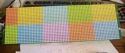
This post is about structure and organization of big RGB LED matrix. Just notes to remember how it works, as paper notes tends to be lost. And it is much easier to find information back in the internet compared to my paper notes.
I completely debugged and reverse engineered the RGB matrix from previous posts. Now it is time to explore, how engineers from Adaptive Micro Systems LLC from Milwaukee, USA, designed it.

Matrix is made from total 1728 LEDs placed on PCB in 24 rows and 72 locums. Total count 5184 discrete diodes. There are two parts (mega-rows) to access upper and lower parts of the matrix: LE_MBI_UPPER and LE_MBI_LOWER (pins 69 and 70 on Cyclone FPGA). One mega row is made from 12 regular LED rows. /LE signal pulse is used to move data from input buffer to output buffer of MBI5026CD chip. (See MBI5026CD datasheet).
All these 12 rows are controlled (via mosfet switches) by regular 74 series chip 74HC154. It is binary to 16 output decoder. Only lower 12 output are used. This chip is connected to FPGA: A0-A3 (HC154[3..0]) to Cyclone (pins 32, 33, 34, 35), OE2 (HC154OE) to FPGA pin 32. Meanwhile OE1 is connected in more complicated and interesting way. There is ingenious protection from system freeze (if matrix could be freezed due to system glitch, the LED may be burned)- there is some discrete parts, diodes, capacitors and resistors which combines to some sort of watch dog. If there is constant clock feed to watch dog (RC_UNKNOWN1, pin 37) the decoder is working. If there is static signal on pin, the decoder is switched off.
All the lines (except first two squares) have 16 RGB LEDs, all connected to three serial-parallel-LED-driver chips (MBI5026CD). Every chip is for one color only, because each color have it own working current. First squares (columns) are missing LED because the matrix is only 72 LED wide, meanwhile “logically” is bigger, 80 LEDs. (it much easier to assume that there is 80 columns in software).
All MBI5026 chips have OE inputs to control output. All connected in rows to control separate colors. OE1 (59) is for upper RED color, OE2 (60)- green, OE3 (61)- blue. Outputs OE4,5,6 (62, 67, 68)- lower part RGB control.
Video output is organized is such way:
Select video data from memory for 10×16 color pixels. Push all data to serial register. Select mega_row to use with LE lines and select discrete line with A0..A3. Why to use LE? Because every “square” have its own SDI input.
Refreshing whole frame, data is fed to multiple zones of the matrix on the same time. This speeds up whole system. In later articles I experimented with various timing systems and it shows, that there is limiting timing “window” available to keep RGB matrix fps high and flicker free.
In this, originally posted at 2008, article I still don’t know how to build full RGB color levels…
