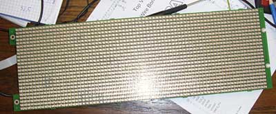
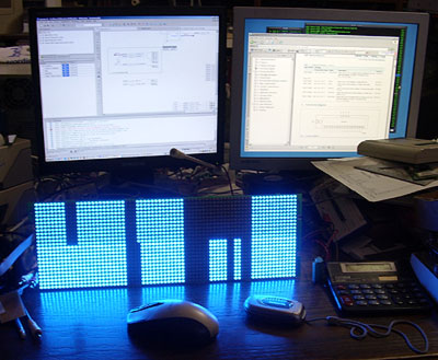
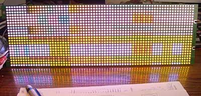
It is RGB LED matrix board!

It is some PCB from Adaptive Micro Systems LLC, USA. This comapny specializes in LED advert production. From simple single color static board to full RGB color outdoor monitor.
Mine LED board is 72 x 24 RBG LEDs. With dinamic connection and some FPGA control. The protocol of the matrix itself was unknow, so I reverse engineered all the connections between chips and programmed my own FPGA code.
As it is FPGA on board, all reverse engineering was quite interesting and “solder free”. I just connected newly populated programming connector with my byteblaster and started software…
And after some time…

After all FPGA pins were traced, the only thing was created whole dinamic display with normal video data.

Here is some random data from clock counters.
It was very interesting: Red and Green LED are powered from 3V source, meanwhile Blue LEDs are powered from 5V source, also all logic chips are powered from 5V (FPGA has it’s own regulator on board).
This is very logical- blue LEDs have higher threshold voltage, RED can work at much lower voltages. So, to keep board cool (regular linear regulators on board), multivoltage PSU is used.
Check original post in Lithuanian language. There is interesting information in comments section.
If you have some questions, take a note, that this post was originally posted in 2008.

Pingback: RGB matrix: organization | Savel brain dump in English!