Google kicked me out

Three days ago, I noticed that mine non commercial web paged didn’t have any rank. One month ago the ranks was 5. Now it is 0. I entered “site:” command in google search and didn’t received any answer. I checked more and discovered that whole domain is deleted from google. There were more than thousand pages listed in google- from selfmade hardware for amiga computer to Lithuanian fauna lovers pages. And this blog is deleted too.

Google banned me
I am deleted!

It is pity, as this domain was not spoiled with trash site and is my oldest work. In fact this domain can be older than google itself. I wrote letter to google, but received only robot mail that they are not responsible for anything. In other words they said “go and fuck yourself”.

Let’s wait few days…

Posted in Anything | 2 Comments

Read telephone ISO cards

When I was using my old computer I wrote software to read ISO 7816 (synchronous) telephone cards. The software was for very old and very nice Amiga computer. 10 or more years passed and I rewrote software for very big, very powerful computer running Windows XP. This software is based on older and smaller software. In fact, it is same program with added card reading and decoding unit. To use software you need Microsoft Visual Basic runtime. Download ISO card reader software and extract it. Start the only executable file. Connect the card to LPT1 port.

ISO 7816 card
The ISO card used in Kaunas as parking payment card

The hardware is very simple. No need any other electronic components- the software is only reading from the card. So data pin is only for reading.

Card connection diagram
Only 3 data lines are used (RST, CLK, I/O). And ground line (GND). Use any external power supply for 5V (Vcc). Or connect the line to USB or joystick port. All other pins are unused.

Start the software and you must see such image:
Card reader interface

The left side is the same as in older program- it is port settings. If you connect to LPT1 port- do not change anything. The right side is card reader part. In the field “bits to read” you can enter how many bits to read from the card. Usually it is 128 bits. Older cards used 64. You can enter here any reasonable amount of bits. The buttons “Read” and “Reset” are self explanatory. You must reset card to read it from the beginning. Or just enter 8 bits and press “Read” button to read card by byte. The “Binary data buffer” field is raw data read from card- you must see string of zeros and ones here. If there is no card, you must see lots of ones. The visible field is smaller, but you can point mouse and select more. And copy to your other software. Or even you can enter your own data. Be careful, the program is not fool proof- I don’t know how it will behave is data will be invalid. The next field is “hex decoded buffer”. Here you can see the binary data decoded to more readable HEX. You can copy the text from here.

Connection diagram and printer pins to use is displayed in program body.

Software is inspired by historical article extracted from Google cache.

Posted in Anything | 2 Comments

Using LPT port as logical scanner and tester

Sometime you need to connect some device to computer and check how it works. It is possible to use printer port for digital scanner and logical analyzer. If using standard print port (SPP) there is 8 output lines and 5 input lines. If using enhanced printer ports all data lines are multidirectional. You can read and write to them. In old operating systems it was very easy to program port. Just access &H378-&H37F port (for LPT2 278-27F) in any program and you can read information. But after invention of protected memory, direct communication with hardware is impossible. So if you have Windows 2K or Windows XP you must use special drivers to do simple jobs. I needed to change some values and has written small program in MS VB. To run it you must have Microsoft visual basic runtime.

Port tool is very simple software. Start it and look to the picture:
Port tool

Just press on left column to change value on data pins (pin2…pin9) and read data from control pins. By default, program reads from LPT1. To use any other port, just enter new value is fields below. The program is not foolproof- you can enter any value and change any port. So, be careful.

Posted in Anything | 1 Comment

Power Saving lamp schematics

As mentioned in previous post, I am examining my energy saving lamps. I am still reverse engineering the schematics of GE lamp. But I found in internet some schematics that looks like real schematics of chinese made lamp.

Power Saving lamp schematics
May contain errors

Few words about the schematics. Rectifier B1 and capacitor C4 is standard. Just making DC from mains AC. C4 is about 400V and 10mkf. The energy for the lamp is stored in L1 inductor, while transformer is used to crate auto-generating generator. Still don’t understand the regulating part of this device.

PTC resistor is used to start the lamp.

In GE lamp the transformer is only with two windings. They use N and P channel mosfets, so they can connect them in parallel.

Posted in Anything | 1 Comment

Blowing capacitors in mainboard

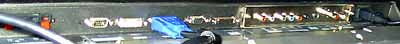
Your computer worked for few years and suddenly it reboots in random time moments. And one day you’ll don’t start it. What is the problem? Maybe it is the capacitor problems? Open computer case and examine the caps (Aluminium cylinders with plastic coating. Aluminum capacitors are relatively large compared to other board mounted components, and in the factories are installed by hand.) on the mainboard. If the top or bottom of the capacitor is bulged or even open, or you can see that something was leaking from it- you found the problem. Why this happened? Because the Chinese manufacturers used cheap capacitors instead of low E.S.R. capacitors that are designed for switching mode regulated power circuits.

Bad cap
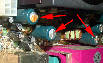
Blown and Leaking Motherboard Capacitors

The caps are typically 1000 … 2500 mkf x 6.3V. If the problem is detected in early stage (when random computer crashed appeared) you can fix it. If the computer didn’t start, there maybe be more serious problems like bad mosfet or even blown up CPU.

You can ask: Can I attempt to repair the board myself ? The answer: If you have considerable soldering skills and are up to date on multilayer “through hole” soldering techniques, Yes!

How to change the caps? Not very big problem. You’ll need few instruments- “powerful” soldering iron (40…60W), new caps and some solder wire.

First check the mainboard and count all caps. You need to replace all caps to make the board run for a while. Go to you radio components shop (radio shack) and buy same capacitors. Only take note to the distance between pins. Also ask the seller for low E.S.R. capacitors that are designed for switching mode regulated power circuits. Don’t take any other capacitor- they will not work or even blow in few minutes. They can kill your CPU!

Make some place with ESD protection for your experiments. If your clothes can make sparks, don’t ever think about repairing your computer.

Heat the leg of capacitor and lift, move it to side for few millimeters. When heat other leg. And in this way, step by step, you’ll remove the cap. Do not use the force, or you can damage the multilayer PCB board. Note the position of the capacitor- they are polarized devices. Usually there is mark on PCB silk screen how the cap must be installed.

Now when cap is removed, clean the holes. Just heat and use special suction device sold in same shop or blow some air to the hole. Or at last, use some toothpick to clean the hole.

Insert new caps and solder them. Trim the wires.

When all caps are replaced test your mainboard. If you are in luck, it will work.

Posted in Anything | 1 Comment

Energy saving lamp

Everybody know that interesting energy saving lamps. It uses regular socket, but looks like fluorescent bulbs. They consumes less power, but produces more light. So called “Watt equivalents”. These bulbs use fewer watts than a regular incandescent bulb while producing the same intensity of light, in most cases. Because most people are familiar with the watts for regular incandescent bulbs, we list the incandescent wattage’s you’re used to buying (like 60 or 100 watts). That way, if you want the light intensity of a 100-watt bulb, you don’t have to figure out which energy saving bulb to buy.

What is inside this lamp. In the base there is small PCB with electronic ballast. The lamp itself is regular tubular fluorescent bulb shaped in special way.
GE energy saving lamp

The ballast of GE lamp is with mosfets: IRFR310 and SFR9310, while other lamp made in China is with regular transistors.
GE energy saving lamp PCB

I’ll try to reverse engineer the electronic ballast schematics. There may be error in it.

Posted in Anything | 2 Comments

RF FM power amplifier

As I mentioned in previous post, the power of my FM generator is too weak. At first I decided to build power amp from scratch, but I remembered, that I had old power amp from some ancient car mobile phone. I was lucky and I found it. The last and most powerful transistor is missing, but I don’t want to jam whole city with my small device. I checked the data sheets of transistors and found that max power of last stage is about 10W. I reverse engineered that part of the schematics. There are lots of stuff in the board. Also there is device to measure output power. I discarded them. Also I didn’t analyzed transistor base power supply (based on LM723H)- I put Vcc and received 0.7V on bases.

schematics
It is simplified schematics of RF power amplifier (Wiring diagram).

T1: 2N5944 npn Pout=2W, Pin=0.18W; T2: 2N5946 npn Pout=10W, Pin=1W. Both transistors work up to 470MHz.

First of all I needed to change the frequency of this amp. Originally it was about 400MHz and I needed about 100MHz. I increased capacity in stage connectors- just added new capacitors 18…47pF. Also squeezed the inductors (after testing I decided to change them) to increase inductance. Also, I added radiator as original was missing.

RF amplifier
RF amplifier
So how it looks like.

The power supply is from some computer. I needed only 5V.

antenna
The antenna is typical quarter wave. According to calculations and using 50 ohm type cable it is 70 cm size. Here is abstract from other internet page:

Another suitable antenna is the so-called “Quarter wave Ground plane”, as shown in figure. It consists of 5 elements of the same type and length as on the dipole. The center one radiates the signal, while the others make a so-called ground plane. D shows how the elements are assembled with a chassis-mount BNC socket. The middle rod is soldered to the center connector, while the lower ones are soldered in the bolt holes. They could preferable be bent under (an soldered to) the next as shown, to give mechanical strength. These rods should not point straight out, but be bent 30-45 degrees downwards. This antenna has 50 ohms impedance, and should be connected to a 50 ohms cable without a balun. It’s important that the antenna is placed high and free. At FM frequencies, the transmitting power don’t affect the range much, it’s more important to have a clear view towards the listeners. If you put a little effort in finding a good location, you can get quite far even with a small transmitter. The antenna should be placed outdoors (preferably on the roof) since both trees and buildings obstruct FM signals. If someone starts asking, remember that such an antenna is good for reception too!

I tested this transmitter and it seams working. Only I need to increase the inductance of L2 and L5. They are too small for lower side of FM band. Also, I need to make radiator work better- now transistors are too hot. Also, I need so tuning device to check the output stage-antenna matching.

Posted in Anything | Leave a comment

Plasma TV 2 – details

As mentioned in other post, one of possible defects of plasma TV is black line of death. The cause of black line is that the one chip glued to display panel is defective. If only contact of the PCB is damaged, the lines are much narrow. If the “distribution” chip is damaged, the line are 4 times wider, or even, the rest of the screen is black. Why this chip can be damaged? The possible cause are: manufacturing defects, high temperature of electrical discharge.

flexible pcb and 4 chips
Here you can see the flexible pcb (un)glued to panel. You can see four chips, four capacitors and four quite big resistors. Typically only the one chip is damaged, but you need to change whole panel. In fact, you need to buy new TV.

It is possible to detach PCB from display panel, but how to glue it back? The pitch of contact pads is very fine.

flexible pcb and 4 chips
(The big blue bars are the millimeters)

Also you need some special glue. This problems is still under investigation.

Posted in Anything | 2 Comments

Plasma TV

From few not working LG plasma TV I made one half working. Just for fun and to test plasma technology. So here is small review of plasma display panel or plasma TV from LG.

Plasma TV repair
Very old (21 years) Panasonic CRT TV and 2004 LG plasma.

Plasma display panel (PDP) is a big glass device- to plates of glass, covered with conductive transparent coating in the form of line. On one plate with horizontal lines, on other with vertical. The space between glass plates are filled with some inert gas. The back plate is covered with special luminescent coating. Put voltage to one vertical and one horizontal line and small plasma discharge is produced on line crossing- small amount of UV is radiated. The UV strikes special coating and it began glowing in basic colors. The back plane is glued to big aluminium plate. It is used to collect heat and cool the plasma display.

In the front of plasma panel there is protective plastic and glass plate. The purpose of this plate is to protect sensitive plasma panel, prevent people from touching hot device and to filter some colors.

In the back of the PDP is lots of electronics. Very big power supply, special computer for signal processing, plasma current supply and the decoders. The decoders-registers are special chips for commutating lines in PDP. With flexible PCBs these chips are glued to PDP glass. These devices are not changeable. So, if you plasma TV shows black line, this means that one of these chips are dead. And you must change all few thousand USD valued PDP if few buck valued chip is dead.

Plasma TV repair
This is the line of death.

Plasma TV repair
Plasma TV repair
The TV has lots of connectors: VGA, Composite, S-Video, component, sound in, speaker out, RS-232, remote controller, ac power

Plasma TV repair
Also there is some noise on this display. Small random dots moving on screen.

To be continued…

Posted in Anything | 3 Comments

Selfmade double sided PCB at home!

To make double sided PCB at home you need: double sided photoresist coated PCB material, some NaOH solution (in mine case- simple drain cleaner), some PCB etching solution (HNO3 in my case), some PCB software, good printer, some transparency foil, glue, UV box.

First design your PCB. I am using freeware Eagle. Print sides separated on transparency. Now glue transparencies and some spacer to form envelope for PCB. Align all the holes. The thickness of the spacer must be equal to thickness of PCB or slightly less.

PCB at home

Remove protective plastic from PCB. Place PCB into the envelope. Dispose useless protective foil.

PCB at home

Place envelope between two UV emitting lamps. Do not move the lamps, pcb and envelope during exposure.

PCB at home

After exposure, develop in NaOH solution. Develop slowly, as strong developer can clean useful parts of the image.

PCB at home

Place the PCB to etching solution.

PCB at home

And check the result. All the holes perfectly aligned. Now it is time to drill few holes.

PCB

Posted in Anything | Tagged | 1 Comment