Security Video

In one company, the security situation is awful and we decided to install security video and record everything. As the facility is quite complicated, we squeezed only to 8 video cameras. In Lithuania you can buy various video in devices, but when you need 8 channels or more, the assortment is quite small. I selected quite expensive, h.264 standard (MPEG-4 part 10), hardware compression video capture card. It is VG8C-RT4:

Video capture card VG8-RT4

The main peculiarity of the card is that it has two Texas Instruments DSPs on board (digital signal processor). The DSP is converting and compressing video, so main computer CPU is not loaded. All free computing power could be used for other interesting purposes.

Video capture: the computer

The computer itself is new too. Maybe it is too powerful for this purpose, but I selected Intel Pentium 4 Duo core, 2.6GHz, 1Gb RAM and SATA hard disk. As I bought computer without any other bells and whistles, without CD/DVD/FD/Monitor, the price is much lower compared to video capture card. Also I selected Intel made, Intel chipset mainboard with extended warranty. I hope, that this computer will do it’s job for a quite long time.

Video capture: 8 channels

Here is the first tests. I need to get familiarized with unknown hardware and software to me. I don’t have so many video sources at home, so I only used 4 channels. I used 3 video cameras’ and one video output from TV set.

Video capture: 4 channels

Four channels in full-screen mode look quite impressive.

Posted in Anything | Leave a comment

New Tubeamp is Born

As local sale of tubes is not satisfactory for me, I decided to build new, full, power amplifier from scraps and surplus components. It will we classic tube amp with double tubes on the output. Why this type? Because it uses lots of tubes and I have transformers.

The main component for tube amp is cool case. Tube holder places are made from old computer case. I used some “branded” and very old computer, so the steel is solid compared to new Chinese made computer cases. The round holes are made using step drills on some drilling machine.

Tube amp case: making the holes

The case itself is some 19 inch box from some old communication device. It was some serial switchboard of something. There was lots of these in local scrapyard and I made one major mistake- I didn’t stored more boxes for myself.

New tube amp: the beginning

In this photo you can see the tubes and PSU installed. Even 75% of tubes are connected to heater. The output stage is made from old classic- 6П3С (6P3S, EL34). The phase inverter and preamp will use some tubes from 12AX7, 12AU7 or 12AT7 range. As I have lot’s of these pull-outs. The mains transformer is with nominal 100W power. This is not some Chinese Watts or other RMS/SRS Watts used in western sale-market world. Nominal power term was used in Soviet time to describe real power of device. This means, that device can handle such power for infinitive time without any harm. Regularly, this means, that power of the device is 50…150% more powerful than stated.

This is the beginning. The rest will come…

Posted in Anything | Leave a comment

Nokia NP5121 to Zyxel Prestige 642R

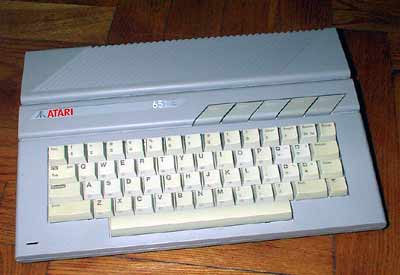
Few years ago, our major internet provider offered NOKIA DSL modems for end users. It was Nokia NP5121. It is very durable hardware. I know few places were such modem is working without any problem for six years.

Nokia NP5121 DSL modem converting to  ZyXEL Prestige 642R router

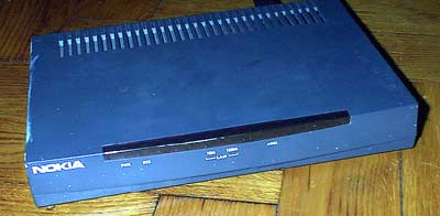
This DSL modem has the secret. With simple firmware flashing you can convert it to more powerfull Zyxel Prestige broadband router/bridge. So if you are sick of that damn PPPoE stuff on your computer, want instant internet access or want to connect more computers on same digital subcriber line, you can reflash your modem.

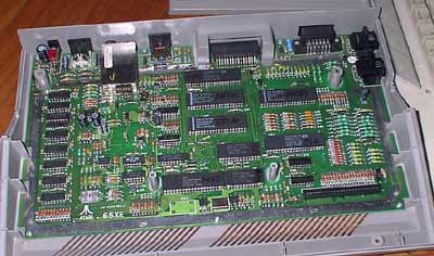
I aquired old Nokia modem from scrapyard. It was with small problem- the power connector was slightly damaged. I resoldered it and I was fully working device. The reprogramming procedure is described in internet. I posted here the shorter version for advanced user. Novice user can use this procedure, but some moment can be harder.

First of all, you must download firmware from zyxel site. Search for Prestige 642 R model and firmaware must be at least R11 version. The older revisions had security bugs and is not recomended to use. Search for file “p642r11.zip”. Also, you must find modem cable with 9 pin connector. You can use cable from old modem or solder it by yourself. Just get two 9 pin d-sub connectors: one male other female. And a peace of UTP CAT5 cable. The pinout of the cable is very simple- pin 1 of male connector is connected to pin 1 of female connector. 2 to 2 and etc. Leave pin 9 not connected.

Connect Nokia to your computer. Selectr serial port in you hyperterminal program, set it to 9600 bod speed, 8 data bits, 1 stop, hardware flow control. Set you hyperterminal program to VT100 terminal emulation.

Switch on modem, press enter and you must see something like:

password

Type “nokia” as default password. You must see command prompt:

MP5121>
MP5121>config reboot

Bootbase Version: V1.05 | 10/17/2000 19:46:36
RAM: Size = 4096 Kbytes
FLASH: Intel 8M

RAS Version: V2.50(AT.1) | 5/24/2001 21:16:14

Press any key to enter debug mode withing 3 seconds.
...........

Press Enter

Enter Debug Mode

You’ll see big list of available commands… We need only one, to increase console speed as using default speed will took lots of time to transfer new firmware. Attention, the prompt dissapeared as we are in debug mode.

ATBA5
Now, console speed will be changed to 115200 bps.

Now we need to reconfigure the hyperterminal to new speed. Set it to 115200.

OK
ATTD
Starting XMODEM download...

This is old settings backup. Set receive mode in terminal and select xmodem transfer protocol.

Total 13384 bytes received
OK

Now we begin new software upload. First of all we need to upload new settings. They are in zip file with ROM file extension.

ATLC
Starting XMODEM upload (CRC mode)....

Now select file send in terminal menu and select xmodem protocol.

CCCC
Total 16384 bytes received.
Erasing..
....
OK

And now main step. The new firmware.

ATUR
Starting XMODEM upload (CRC mode)....
CCCCCC

Now we need to send the file with BIN extension from same firmware archyve.

Total 1010048 bytes received.
Erasing........
........ (lots of dots).......
OK
System Reboot...
Console speed will be changed to 9600 bps

Reconfigure terminal software to 9600 bod speed. Enter new default password “1234” and see new bright MP5121 router configuration menu:

DSL router config menu

Posted in Anything | 3 Comments

Last view to ATI and nVIDIA GPUs

Today I decided to break apart few video cards. There was box of old nVIDIA and ATI video cards. With various connectors and RAM sizes. Here is the collage from GPU images:

ATI and nVidia GPU

To prove that it is broken apart cards, here it is the small photo of GPUs cut off the cards:

ATI and nVidia GPU

As I remmember the cards were:

ATI: Radeon 9600 XT, R360…
nVIDIA: Geforce FX, FX5700LE, Geforce 6500, Geforce 6600…

The guillotine scissors (tinsnips) cut both manufacturers card in the same way. Maybe it was harder to cut ATI radeon 9600 cards- it was because of the RAM chips placed on both sides of PCB.
The heatsinks were very easy to remove- just place screwdriver under it and pull. Some low power ATI cards with passive heat sinks were glued to GPU. But using strong screwdriver can solve everything- just more strength, and heatsink is flying across the room.

The photo contains only the part of video GPUs I removed. I think I just broke apart card of total $1500 value. And now I feel much better 🙂

Posted in Vandalising | Leave a comment

For beginners: regulated linear regulator

If you need simple regulated power supply, you can build it using typical old chip LM317 (LM117). Here is the abstract from datasheet: The LM317/117 series of adjustable 3-terminal positive voltage regulators is capable of supplying in excess of 1.5A over a 1.2V to 37V output range. They are exceptionally easy to use and require only two external resistors to set the output voltage. Further, both line and load regulation are better than standard fixed regulators. Also, the LM117 is packaged in standard transistor packages which are easily mounted and handled.
In addition to higher performance than fixed regulators, the LM117 series offers full overload protection available only in IC’s. Included on the chip are current limit, thermal overload protection and safe area protection. All overload protection circuitry remains fully functional even if the adjustment terminal is disconnected.
Normally, no capacitors are needed unless the device is situated more than 6 inches from the input filter capacitors in which case an input bypass is needed. An optional output capacitor can be added to improve transient response. The adjustment terminal can be bypassed to achieve very high ripple rejection ratios which are difficult to achieve with standard 3-terminal regulators.
Besides replacing fixed regulators, the LM117 is useful in a wide variety of other applications. Since the regulator is “floating” and sees only the input-to-output differential voltage, supplies of several hundred volts can be regulated as long as the maximum input to output differential is not exceeded, i.e., avoid short-circuiting the output. (end of abstract)

I only can add, that the power dissipation rule as mentioned in older post about linear regulator is working here too.

LM317 regulator schematics

LM317 is usually made in TO220, transistor package. There is difference in pinout compared to 78XX series regulators. The output of the regulator is connected to the screw tab. There are also other types of package. SMD packages are made too.

LM317 regulator circuit diagram

This is typical circuit from the datasheet. Theoretical output voltage is from 1.2V to max about 28V. Using floating regulator trick, the output can be higher. Max current with TO-220 case is about 1.5A (you max calculate power dissipation and select proper heat sink).

LM317 regulators

I connected circuit on the breadboard. I used trimmer instead of resistors. I think, it is possible to use any trimmer form 3K to ? kilo-ohms. Somehow I didn’t managed to get 1.2V output even when I connected regulating pin to ground…

Posted in Anything | Leave a comment

For beginners: simple linear regulator

This blog entry is for beginners. Sometimes I receive letter with questions from beginners.

So, the question: how to build very simple voltage regulator? For fixed (3.3, 5, 6, 12, 15V) or adjusted output. The simples way is to use special chip- linear regulator. The unnecessary voltage are disposed by the heat. So this type of regulator typically use heat sink. As bare chip version is only of a few watt power output.

7805 stabilizatorius

According to the datasheet, there must be some capacitors. But the main element is three leg element. Center connector and the screw tab is connected to ground.

The chip can be named with various additional symbols, but the main series of those chips carry 78xx mark. For example, the 5V regulator is named 7805, 12V – 7812 and etc. The full name for chip for national semiconductors is LM7805C. The low power version carry 78L05 mark on the body of the chip.

Soviet copy of the chip is called “KREN”. It is from shortened marking. The full name of Russian chip is КР142ЕН5 (for 5V version). The chip is carrying shortened version “КРЕН5”, and it sounds like “KREN5”.

TO220 case chip can pass 1…2A current (depends of model). Typically the chip has build in protection from over current and overheating. But always check the datasheet. Max temperature of the case is 70…80 degrees of centigrade. Theoretical maximal power from the chip is 20W using endless heat sink. Bare chip can dispose about 2W of heat. Using real heat sink- 5…10W. How to calculate this power? Just few lines of math:

For example, we want to build some PSU to use in the car. Typically, the power in the car is from 12V (when engine is off) to 14V (with started engine). Assume that output will be 5V @ 1A. We must calculate with biggest possible values.

Udrop=Ucar-5V=14-5=9V

The power dissipated on the regulator:

P=U*I=9*1=9W. (And is the current increases, the power is going very high- at 2A it is 18W)

So, we must dissipate 9W of heat. It is more than 1…2W, so we need heat sink.

Sometimes, when connecting regulator to wall “brick” adapter we must use the heat sink, as output from rectifier is much more than stated on the label. Measure the voltage with required load. I’ve seen adapters where output was 25V at 250mA load when label was 12V!

So:

P=20*0.25=5W (!) And we need heat sink with this adapter. Especially if it is placed in closed box…

One more parameter- max input voltage. It is about 35V for 7805. Read the datasheet.

Other interesting parameter minimal dropout voltage. This means how the voltages must differ from input to output to put linear regulator to normal working condition. This can be obtained from datasheet. For example, 7805 need nor less than 7.5V input. There are new series of low dropout voltage regulators. Like LX8383. It need on 1.3 … 1.5V dropout for normal work. The max current is much more- 7.5A max, but the input voltage is much lower.

How to make adjustable regulator? Very simple, just enter resistor network to divide voltage:

adjustable output voltage

Similar resistor network can be used with 78xx chips. It is possible to put trimmer and to adjust output voltage. Later, it is possible to measure the resistance of trimmer’s halves and replace trimmer with regular resistors.

To adjust output we can place zener in the gnd line. The output voltage will be equal to regulators voltage plus zenners breakout voltage. For example 7805 and 1.5V zener will output 6.5V.

Posted in Anything | 2 Comments

ZX Spectrum

Today I visited some old junk shop to check electricity counter and found lots of interesting stuff. I bought two things- Sega Game Gear and Sinclair ZX Spectrum personal computer. I payed 3LTL (~1USD) for Speccy.

It is original ZX Spectrum computer brought to Lithuania from United Kingdom. It is one of the first personal and game computers in the world. Original copyright on the PCB is from 1983. So it is 23 years old!

This computer was reverse engineered and most cloned 8 bit computer in Soviet Union.

ZX Spectrum

Original ZX computer is smaller than its clones. You can hold it on you hand. One interesting moment- the power supply pin-out is reversed to standard ones from Internet switches/routers and other 21 century equipment. You can’t use wall brick adapter with speccy. If you plug it, the 7805 chip short circuits the PSU.

ZX Spectrum

Inside there are few chips. The most of them are RAM chips- ZX spectrum uses dual RAM. It was some sir Sinclair’s crazy idea to use separate video RAM in same 64K address space. As I know, only one ZX clone used dual RAM. All others used same RAM chips for all memory.
Big chips are CPU, ROM and some custom chip. Small chips are standard TTL logic.

ZX Spectrum

I always run this special program. This program is for my good friend who had ZX. I was using Atari computer. Atari is the best! 🙂

Posted in Anything | Tagged , , | 4 Comments

LC meter

LC meter based on LM311 and PIC16F84 micro controller. 0.0pF – 1uF and 0.0uH – 0.5H range. Quite precise meter.

My Machtech tester is capable of metering the capacitors, but is very complicated to measure short lead capacitors, not speaking about SMD ones. Also, I needed to measure the coils. In www.sprut.de I found some LC meter schematics. It was quite interesting and capable to measure very small values. It is based on the LC generator frequency difference when additional capacitance or inductance is attached. The only precise element in the meter is capacitor. Also, it is possible to use trimmer and set the meter to required level of precision.

The meter is based on LC generator on LM311 and microcontroller PIC 16F84 (16c84). The indicator- standard alphanumeric LCD display. From old Hagenuk cable detector I removed very nice LCD displays with big numbers and symbols. They are as twice as big as normal. The internal jumper JP1 is used to switch meter from nanofard mode to microfarad. It is useful for old schoolers 🙂

The meter under the construction:

LC meter

Original schematics are in the author pages.
Preview of the schematics:

LC meter circuit diagram

I’ll place this meter and other stuff to standard 19″ rack from some old switch. There is original PSU from the switch. It gives me all needed voltages and is quite powerful.

According to mine idea there will be: LC meter, frequency meter, wide range high frequency functional generator with sweep option.

Posted in Anything | 3 Comments

Fender-wing change

Lithuanian only blog entry.

Abstract:

I decided to change front fenders for my car. As they are not original, I needed to try if they fit to the car. So one weekend was committed for car repair.

All you need is 3 spanners (wrenches) with metric size 8, 10 and 13. Also philips screwdriver and old blunt knife.

VW tuning :)
(please wait, it is 600kb animation)

First of all, remove grid with logo of the VW car. It is connected only with plastic retainers (fixers). Then, use wrench number 10 and remove bumper. Pull it to the front ant remove. Do not forget wires- disconnect them.

Now remove plastic protection under the fenders. They are screwed to the body of the car by several screws. Original are number 8, if repaired- then typically replaced with philips type.

Now you can remove the fenders. They are bolted to the body of the car with number 10 bolts and screws. 4 in the bottom and few on the top. One bolt is number 13- where capote is grounded, near antenna. If fender is original, it is glued to the body. Use knife here.

Posted in Anything | Leave a comment

Li-ion technology

The beginning was the damaged battery from my old video camera. The old battery for it was made from 6 (six!) NiMH cells. The cells were worn out and didn’t hold too much charge. Full loaded battery was emptied in 40 minutes of filming. Also, my mother managed to short circuit the battery and everything finished with lots of fumes and explosions. The original battery for mine camera is very expensive as camera is very old and quite rare. Now I needed to build new battery using cell bought from shop. There is two type of cells which can be used in my battery: NiMH and Li-ion.
I needed either 6 cells of NiMH technology or two of Liion. (Original battery is Li-ion). The price for both types of cells are quite high. The project was closed for a while. Recently I received few batteries from notebooks. They are build in circa 2005 and the cells are quite good. The batteries where discarded due to typical problem- on cell failure. The battery is 14.8V and 4400mAh. Inside there are 8 cells. So the battery organisation is 4×2 and cell is 2.2Ah.

Li-ion technology

Next stage- proper Li-ion charger for double cell battery. I digged few types of mobile phones, but all of them had only one cell charging controller. The controller is typically made by Benchmarq (now Texas Instruments). From good people, I received two sample chips for dual cell charger. It is BQ2057. And it was very good that I receive two chips. The first chip was damaged during construction. The schematics or the circuit diagram is typical, from datasheet. The transistor I used is from old HDD controller, some PNP, 2A one. Thermistors were from notebook batteries.

Li-ion charger schematics

The circuit was working, but as it is linear regulator, quite a lot of energy are waisted on regulating transistor. As wall plug is giving about 15V and the current is quite big for 2Ah cells. The transistor is getting very hot. So from old scrap I removed switching mode power regulator (from old LCD monitor stand). It is LM2576-5 (fixed output voltage). I attached trimmer to feedback circuit and regulated output up to 9.4V (assuming that voltage drop on power transistor is about 1V and the battery need to be charged to 8.4 or 8.2V).

step-down PSU

Both PCBs were glued together to one small unit. In the upper photo, on the left you can see the charger. I charged 5 pacs of cells. But one morning I found my charger dead- there was hole in the BQ2057 chip. I measured all the voltage around the chip and everything was in normal. It is quite mystical failure. Now I am waiting for new chips and I’ll try to build better charger. (hoping to receive switch-mode charger chips with “all included” version).

Posted in Anything | Leave a comment