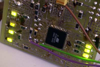
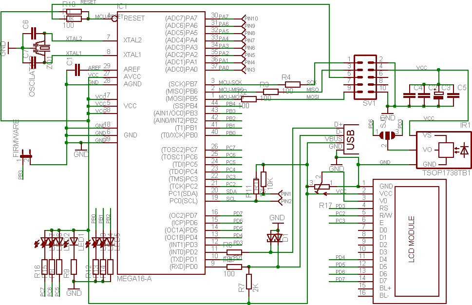
There are lots of chips with serial control. Some of them use Philips I2C buss. There two data lines and two power lines to transmit all data. There DTMF encoders, switches, Dolby surround audio processors, multiplexers and many many other devices. Just open any TV set and you can find some- like TV tuner. ATMEL chip has build in serial interface, but it is called TWI. In my PCB there are two bigger SMD pads to connect I2C buss. Don’t forget to solder 10K pull up resistors.
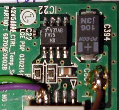
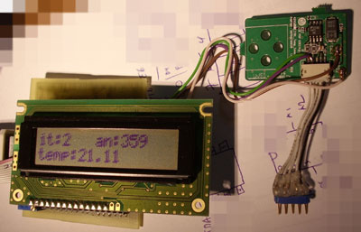
For testing TWI bus I selected I2C temperature sensor. It is LM75 or any other clone. I am using small PCB from old plasma display panel with Fairchaild FM75 chip. It is smarter and more precise clone of original LM75. FM75 is backwards compatible with LM75. It has more precision and this means more data bytes available to read. At full precision it used 12 bits for temperature. In my software I used simplified algebra to convert 1/16 fractions to metric system. For more precise calculations, read FM75 and LM75 datasheet. And maybe AD7416 datasheet too.
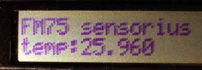
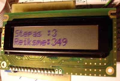
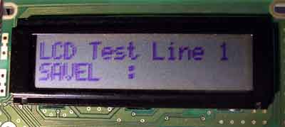
I am using i2c.c from internet, from USB Tenki project. This project is very interesting, pay a visit to original Tenki web page for more advanced device. lm75.c is from same source. LCD modules are same as in older my web blog posts. When you connect your LM75 chip, don’t forget to check the device address- base address is the same, but user selected pins maybe connected in other way.
Programa: 20070919.zip.
With these chips and software example it is possible to build some thermostat project. But don’t write all controll stuff for ATMEL chip. Read the datasheet again and use LM75 thermostat option. Use ATMEGA only for control, display and setup.