
Now we need to test PCB and MCU. To test this hardware we need to run some program. And to build program we need tools. I downloaded and used free software from internet. WinAVR package: http://winavr.sourceforge.net/. Also, I am using programmers notepad2. It is useful tool for MCU programmer.
First program is simple LED flasher. We will test if MCU is working and if all LED diodes are working and all pins of MCU is properly soldered. The only LED will be on all the time is power LED. As the photo is made with long exposure, it seams, that all LEDs are on. In real, they are flashing in binary way.
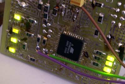
(My printer is dead, so the PCB is ver ugly)
Software source and hex file: 20070916.zip
Software is very simple- we just set some pin to output and start counting cycle. Counting results are set to output pins. It is bad programming practice to put whole byte to several pins. In real world we need to alter only these bits we need to change- never put data to unused pins or input pins. But this program is for testing only.
Few comments. As I mentioned, mine LPT port is damaged, so I am using add on card. So, edit “makefile” for your programmer. You must check the “program”section. In my version there is few words to describe port address of my add on card:
program: $(PRG).hex

	avreal32 -pBC00 -ab -e +$(AVREALMCU)

	avreal32 -pBC00 +$(AVREALMCU) -ab -w -c $(PRG).hex -v
Just change -pBC00 to you port. Use “avreal32 -h” for more information. Or, if you use other programmer, replace these line according your programmer manual. Or, don’t use “make program” menu item in editor’s toolbar.
Also, some words for absolute beginners. Typically you can find information about simple things- everybody know how to do and they even don’t think, that somebody will not know how to do simple compile things. So, to compile software use “make all” menu item from programmers notepad or from CMD prompt. The computer will print lots of stuff on screen, but the main message is at the end:Process Exit Code: 0 and if you don’t see any ERROR.
Command “make clean” or Tools->[WinAVR] Make Clean, cleans all compiled files. So if you change something in the source, use make clean to be sure.
And the last menu item, make program or Tools->[WinAVR] Program we program firmware to MCU.
Few words about security bits. Carefully read original Atmel documentation. Sometimes these bits are mixed in various documents. Some tell that “set” means write 1, others- vice versa. It is possible to set MCU to “closed” mode and it will not be visible by programmer. As I am using “second hand” MCU I don’t need to change fuse bits. Mine bit looks like this:
Fuses

  OSCCAL	= AD, AB, A7, A8

  BODLEVEL  	= 0

  BODEN     	= 1

  SUT       	= 2

  CKSEL     	= F

  BLB1      	= 3

  BLB0      	= 3

  OCDEN     	= 1

  JTAGEN    	= 1

  CKOPT     	= 1

  EESAVE    	= 0

  BOOTSZ    	= 3

  BOOTRST   	= 1
As it is still working I am not changing any bit. Use this online tool http://palmavr.sourceforge.net/cgi-bin/fc.cgi
You can find HEX file in archive, so you can test hardware without any compilation.