
(AI translated from 2022.05.02)
Short prehistory: we collected some PCBs with STM32F1031 chips and an unknown LCD. The LCDs were of two types, and the PCBs were also of several variants. Some had another STM32 BGA chip and ROM/RAM chips. Other PCBs were almost empty or damaged. All had Bluetooth and various small components.
We easily identified various connectors (fortunately, not all PCBs were covered with lacquer), and some simple components like LCD backlight (or something else) went through transistors, so that was also easy to figure out. But the LCD remained a mystery. There were indeed two types of LCDs – a smaller one, black when off, and a larger one, white. Both screens were graphical, as the original firmware indicated “update software.” The initial software seemed to be universal for both boards, and we discovered that the boards were from Husqvarna automatic lawnmowers.
Unfortunately, there was no information about the LCD screens or controllers. So, I started trying various LCD screens with a similar number of pins… Based on voltages and the signals sent by the original firmware, I determined roughly where the data was, where WR or similar signals were.
The smaller LCD was very similar to the ST7565, and everything was roughly clear there. The large LCD was completely unclear.
It also seemed very strange why such a weird connection to the MCU was chosen:
PD0=D2
PD1=D3
PD4=RD
PD5=WR
PD7=CS1
PD14=D0
PD15=D1
PE3=A0
PE7=D4
PE8=D5
PE9=D6
PE10=D7
But I didn’t bother too much. The LCD was more important. There were problems with the larger LCD – it was very similar to UltraChip series controllers like UC1610 or UC1611. However, not all commands worked. The problem was that many commands were common to the entire series of chips (or even chips from other manufacturers), while other commands were ignored or similar.
And the grayscale bit sequence of the LCD screen itself was surprising. At one point, I thought a color screen controller was attached to a black-and-white LCD screen. Another thought was that I misread the pinout (definitely not, see below).
While playing with bits, I wrote some software for screen control. However, to draw an image on the screen by pixels, you need to read the information from the screen. This can be done in “bit bang” mode, and with STM32F103, it happens quite quickly. But it all seemed very stupid. I read the instructions, Googled, and examined STM32Cube, and it turned out there’s an FSMC mode unknown to me, where some MCU pins become DATA, ADR, and control signals (WE, CS, etc.). Then reading from or writing to the LCD (or some SRAM) becomes a simple operation – “writing and reading from RAM”:
*(__IO unsigned char )(LCD_DAT_ADDR)=d;
d=(__IO unsigned char *)(LCD_DAT_ADDR);
And our LCD is connected exactly as an FSMC device (hence the weird LCD pinout).
However, nothing worked for two days. The documentation was quite vague and seemed very illogical at first glance. The problem was related to data bus widths and addressing. The A0 pin of the LCD, which separates data from commands, was attached to the A19 pin. The level of this pin had to be regulated by address bits:
//Our LCD A0 is connected to the A19 pin.
#define LCD_CMD_ADDR 0x60000000
#define LCD_DAT_ADDR 0x60080000
However, nothing worked. It turned out that in my example software, it was not “unsigned char,” but “unsigned int” (aka uint16). In other examples, there were even 32-bit variables. And worse – several articles stated that if 16-bit reading is used, the address shifts by one bit, if 32-bit, by two bits. But that didn’t help either because my main mistake was assuming that reading 16 bits from an 8-pin port, the lower bits would have the necessary information. It turns out that’s not the case. As far as I understand, the STM chip adjusts at the hardware level to the “bus width” and even performs several reads or writes. If configured illogically, everything works illogically.
Therefore, if you need to read a BYTE from an 8-wire bus, you need to read a BYTE in C language. I am still not sure if reading a WORD from a BYTE does not involve double reading. This needs to be checked further because the LCD screen software could be more optimized. And regarding the address, it is also a bit unclear to me, but byte, word, and longword addresses are correspondingly shifted if we want to read them. In ARM, there might not be the issue that is present in MC68000, where you cannot read byte-by-byte or similar from odd addresses…
I wrote a lot and quite unclearly, but this is my “brain dump,” and this information is for me to remember how to enable FSMC mode on STM32F103. What else does FSMC give us? DMA.
To make the article more interesting, here’s a photo:
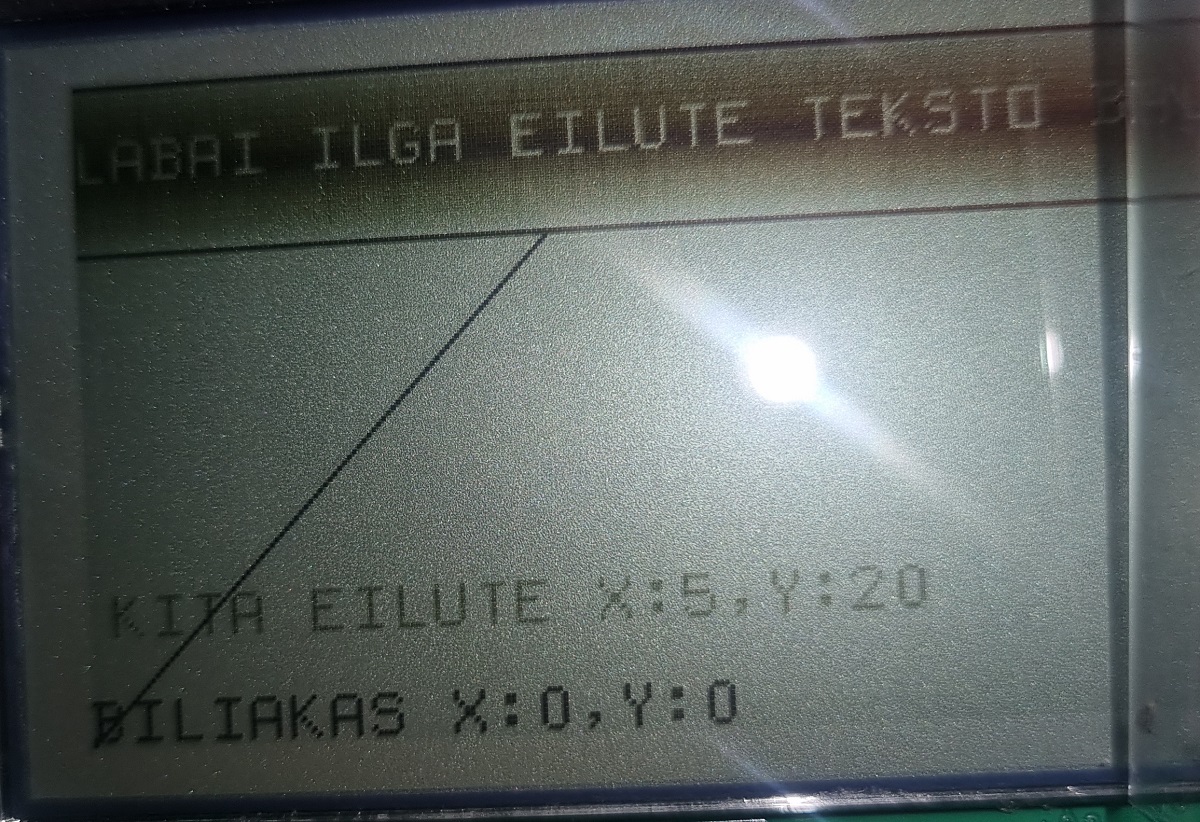
That’s the large screen, unfortunately, without backlight on. Using a somewhat strange “classic” TI99 font, which may not be suitable for this screen.
And even three variants of source code with everything: small screen bitbang, large screen bitbang, and large screen FSMC: Husqvarna LCD and STM32F103 FSMC.
All the source code is indeed not tidied up, there are many remnants of experimentation and reverse engineering.
The same board supports several types of LCD screens with a 24 PIN connector (one LCD was with PE12864URT): PINOUT pdf.
- Not all STM32F103 support FSMC. Here it’s STM32F103VGT6. ↩︎