(AI translated, original post from 2022.04)
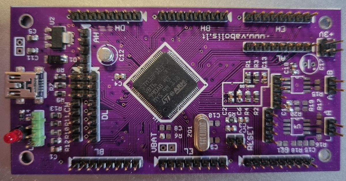
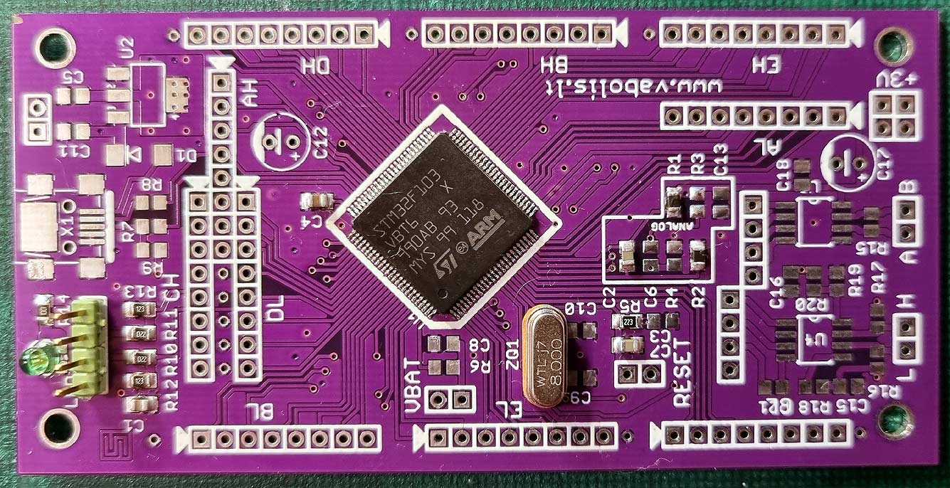
Do you remember, I wrote about the remnants? About the mountain of STM32F103VBT chips with slightly bent legs? So, I made an experimental board. I wired ALL the pins to 0.1″ connectors. I also added some RS485/CAN attachments in the empty space.
It is really difficult to solder the chip when the legs are slightly bent. But on the second try, it seemed to work. The diagnostic software shows that signals pass through all the pins and there are no short circuits. Of course, the minimal amount of components and power is provided from the “serial debug” port. By the way, if you accidentally block the “serial wire,” it’s not a big problem, short “Reset,” start programming, and then disconnect “Reset.”
The labels “AL”, “AH”, “EL” and so on are pin groups. For example, AL – PA(0-7), the “low” part. AH is PA(8-15) and so on.
All files:
- Diagnostic firmware – source code, STM32Cube file, compiled HEX.
- Gerber files – Standard Gerber files if you suddenly want to order a PCB.
- Schematic – The schematic of this board. Quite roughly drawn (pdf).
- PCB illustrations – PCB views of this board (pdf).
- BOM.
Attention, the jumper SJ1 on the bottom side of the PCB is already shorted to GND. That is, BOOT0=GND. If you need a different value, you need to cut the track on the jumper and solder the appropriate resistor.