
From old device I removed controlles graphic LCD screen and part of the mainboard with Toshiba controller. As controller was with all hardware, I just connected everything with air wires to PC printer port using my breadboard.
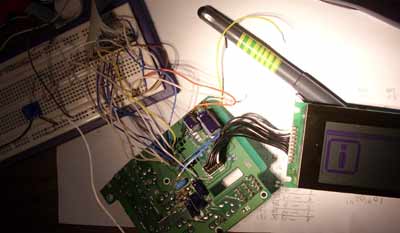
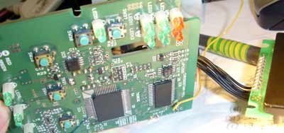
There are two main chips on controller “board”- the controller itself (Toshiba T6963C) and small RAM to store data. All other stuff left on board is leftover from the other device components and negative power supply.
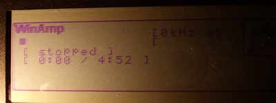
This image show the output of LCDinfo program. As this program uses character and graphics features of the controller, you can see text lines and background image. They are independant.
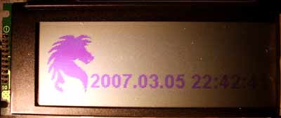
This is the output of LCDStudio program.
Connection diagram is very simple. Printer port pins are connected to toshiba controller pins. Printer’s D0-D7 (pin 2-9) are connected to controller’s D0-D7 (pins 10-17). RESET pin (2) is used only to reset the device. It may be connected to push button and ground to anable manual reset. Printer’s port pin 14 is connected to CE (pin 20), pin 16 to C/D (pin21), pin17 to RD (pin19), and printer’s port pin 1 is connected to WR (pin 18). That’s all.
This page is loved by fucked spammers. I have almost all spam comments to appear in this page. So, fucked spammer, even do not try to post your spam comments in this weblog. All comments are moderated by Administration.
And fora.pl spammers don’t have brains. What ever you can get from polack.