
This article is also an introduction, but this time a bit more practical- USB to serial port (COM) dongle. This tutorial will show how to create USB devices from “canned” software using only STM32CubeMX. For this example I used some scrap board with an STM32F102 MCU. All written in this article can be implemented in bluepill or any other STM32 chip with USB support.
I used this board because it has RS485/422 drivers on board and I was testing some concepts for my next bigger project.
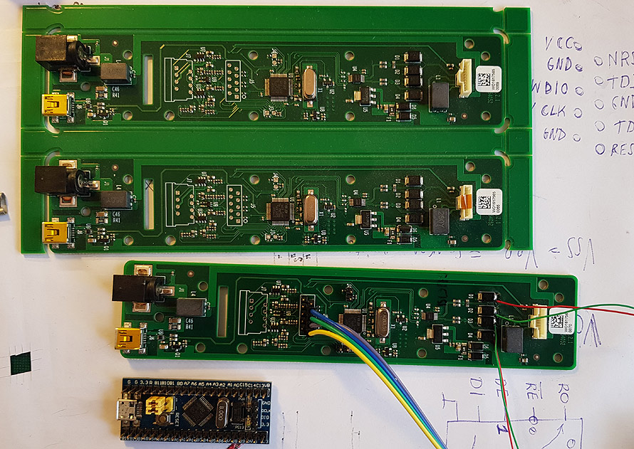
I have three of these boards. For testing, I closed the RS422 loop to itself. Now I have hardware echo and I can test software on heavy loads- transmission and receiving at same time.
Lets begin…
Start STM32CubeMX software and select your MCU, at my example it is STM32F102C8T.
I am using here UART number 2. ‘Cause it is connected to hardware interface. Two pins used.
We will build the USB device. Another two pins reserved.
My RS422/455 transceiver chip use two pins for flow control. For this experiment, I will not change these control pins, so I set levels in Cube program. One pin high, other- low.
I mentioned in the previous article, that I forgot to show serial debug settings. Here it is. Without these pins dedicated to programming, you need to press hardware reset before starting ST-Link and release after some time. Not a very comfortable task. If you have spare pins- leave them for debug.
Clock configuration. It is done automagically. Only check if your external crystal is the same speed as in software. Another two pins reserved.
Now more serious stuff:
We ask Cube to create all the software for USB CDC (virtual com port) device. It is so called midleware- something between low level USB routines and user program. Midleware is responsible for creating USB device, enumerating and proper initialization.
If we want a non blocking serial device, we must check if UART global interrupt is enabled. Leave it checked if you want to use DMA transfers. There are some problems with this tutorial software- it is very simplified and there may be some bugs and software collisions when sending more data then UART can handle. For the non tutorial version I used more checking and bigger circular buffers. For demonstration purposes I leave it as simple as I can.
Press clock issues resolver:
It will check and repair clock configuration- USB device need some strict clock speeds:
From 8MHz crystal source clock is passed to PLL, here it is multiplied by 6, up to 48MHz for USB hardware. Same, 48MHz system clock is used for all our calculations (it may be slower or faster) and it is used to clock our peripherals.
I am using “makefile” IDE. Fill up the name of the project and location of the files and press “generate code”.
Now it is the scary part- start a text editor and look at the source folder “Src”.
The First “victim” is the “main.c” file… We just look at it and change … nothing. All our computations are done in interrupts, so the next file to edit is “stm32f1xx_it.c” – “it” means interrupts.
First, we create our “big” 🙂 , one byte size circular buffer for serial data:
/* Private variables ———————————————————*/

/* USER CODE BEGIN PV */

uint8_t baitinisbuferis;

/* USER CODE END PV */
Now scroll down, where is USART interrupt function:
/**

* @brief This function handles USART2 global interrupt.

*/

void USART2_IRQHandler(void)

{

/* USER CODE BEGIN USART2_IRQn 0 */
/* USER CODE END USART2_IRQn 0 */
HAL_UART_IRQHandler(&huart2);
/* USER CODE BEGIN USART2_IRQn 1 */
HAL_UART_Receive_IT(&huart2, &baitinisbuferis,1); //vieno baito buferis, uzsakom interupta. Nes uzsakymas vienkartinis, sunaudojus, reikia vel uzsakyti.
/* USER CODE END USART2_IRQn 1 */
}
Here it is one interesting moment. HAL_UART_Receive_IT enables USART interrupt, but only for a single shot. After data processing, the user must request HAL for next USART interrupt. This is done because the user program may be outside the interrupt processing function and with auto interrupt, it may be fired before finishing the previous byte. Also, maybe some problems while interpretation of error handling.
Another not very well documented for beginners function is “call back”. Real INT function does almost nothing, but it is called “weak”* (see C manual) function “HAL_UART_RxCpltCallback”. We must create our own version of this function:
/* USER CODE BEGIN 1 */

/* programulka kuri paleidziama kai musu uzsakytas baitas atvyksta.

*/

void HAL_UART_RxCpltCallback(UART_HandleTypeDef *huart)

{

if(huart->Instance == USART2)

{

CDC_Transmit_FS(&baitinisbuferis,1); // ka gavo, ta ir issiunciam

}

}

/* USER CODE END 1 */
We must inform compiler that CDC_Transmif_FS is valid function. It can be done using extern command or by including “h” file:
/* USER CODE BEGIN Includes */

#include “usbd_cdc_if.h"

/* USER CODE END Includes */
This all software above do simple task- when byte is received via USART, it will be immediately transmitted to USB device. This is COM->USB part of the dongle. Next part, USB->COM, is written in other file, “usbd_cdc_if.c”. Here are user routines for CDC configuration and receiving. Also, here we can find our “transmit” function. USB_CDC file do not know anything about our USART device, so we need to add USART handler definition:
/* USER CODE BEGIN PV */

/* Private variables ———————————————————*/

extern UART_HandleTypeDef huart2; //va cia tikrai nezinau kaip reikia daryti, kad imtu globalini huart2

/* USER CODE END PV */
Now we need to add some crazy stuff to make our “USB dongle” usable with the Windows operating system and Putty program. It is not very well documented, but some windows software wants to set serial speed settings and read it all back to check if the USB serial device is configurable.
Some comment: many people do not understand why there is serial speed and other settings in virtual USB devices and when they are used. If our device is fully virtual it can ignore all the settings- data is transferred using the USB high speed layer in bursts. But, if this virtual device is using any real world serial hardware, these settings can be applied to real UART ports. In my example I am using windows port speed for real world port speed. All other setting are ignored.
Here it comes:
/* USER CODE BEGIN PRIVATE_VARIABLES */
 //cia kaip ir buferis, nes windows nori ne tik konfiguruoti porta, bet ir paziureti ar jam pavyko.

USBD_CDC_LineCodingTypeDef linecoding=

{ 115200, /*greitis */

0, /*stop bitai */

0, /*parity */

8 /* bitai */
It is temporary buffer (structure) to keep COM port settings. Scroll down to setting part of the software listing:
static int8_t CDC_Control_FS(uint8_t cmd, uint8_t* pbuf, uint16_t length)

{

/* USER CODE BEGIN 5 */

switch(cmd)

{

… …

case CDC_SET_LINE_CODING:

//cia kompas siuncia UARTo konfiguracija.

linecoding.bitrate= (uint32_t) ((pbuf[0]) | (pbuf[1]< <8) | (pbuf[2]<<16) | (pbuf[3]<<24));

linecoding.format =pbuf[4]; linecoding.paritytype =pbuf[5]; linecoding.datatype=pbuf[6];

// Realaus COM porto perkonfiguravimas:

HAL_UART_DeInit(&huart2);

//atjungiam

huart2.Init.BaudRate=linecoding.bitrate;

HAL_UART_Init(&huart2);

//ijungiam per naujo break;

case CDC_GET_LINE_CODING: //o cia windows ir putty nori nusiskaityti parametrus ir suzinoti ar sukonfiguravosi.

pbuf[0]=(uint8_t) (linecoding.bitrate); pbuf[1]=(uint8_t) (linecoding.bitrate >>8);

pbuf[2]=(uint8_t) (linecoding.bitrate >>16);

pbuf[3]=(uint8_t) (linecoding.bitrate >>24);

pbuf[4]=linecoding.format;

pbuf[5]=linecoding.paritytype;

pbuf[6]=linecoding.datatype;
break;
… …
Now windows Putty serial terminal program will start without any error. One part of the listing just receives configuration data, stores it and re-configures port speed. Other part just reports “current” settings back to Windows OS.
Almost done. All settings done and now it is transmission of the data:
static int8_t CDC_Receive_FS(uint8_t* Buf, uint32_t *Len)

{

/* USER CODE BEGIN 6 */

USBD_CDC_SetRxBuffer(&hUsbDeviceFS, &Buf[0]);

USBD_CDC_ReceivePacket(&hUsbDeviceFS);

HAL_UART_Transmit_IT(&huart2,Buf,sizeof(Buf)); //ka gavom per USB, ta dedam i UARTa.

return (USBD_OK);

/* USER CODE END 6 */

}
That’s all Folks! If you can not create your own listing, here is full source code, compiled binaries and STM32CubeMX project file for USB COM dongle.
Warning! It is only the demo program. At heavy loads it may stall or/and miss bytes of data.
Link to source article: https://www.vabolis.lt/2020/04/11/arm0010-stm32cubemx-usb-2-com-dongle/
*) The weak attribute causes the declaration to be emitted as a weak symbol rather than a global. This is primarily useful in defining library functions which can be overridden in user code, though it can also be used with non-function declarations.