
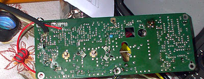
As I mentioned in previous post, the power of my FM generator is too weak. At first I decided to build power amp from scratch, but I remembered, that I had old power amp from some ancient car mobile phone. I was lucky and I found it. The last and most powerful transistor is missing, but I don’t want to jam whole city with my small device. I checked the data sheets of transistors and found that max power of last stage is about 10W. I reverse engineered that part of the schematics. There are lots of stuff in the board. Also there is device to measure output power. I discarded them. Also I didn’t analyzed transistor base power supply (based on LM723H)- I put Vcc and received 0.7V on bases.
It is simplified schematics of RF power amplifier (Wiring diagram).
T1: 2N5944 npn Pout=2W, Pin=0.18W; T2: 2N5946 npn Pout=10W, Pin=1W. Both transistors work up to 470MHz.
First of all I needed to change the frequency of this amp. Originally it was about 400MHz and I needed about 100MHz. I increased capacity in stage connectors- just added new capacitors 18…47pF. Also squeezed the inductors (after testing I decided to change them) to increase inductance. Also, I added radiator as original was missing.
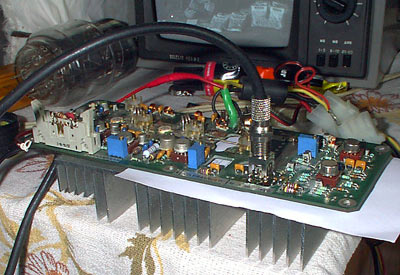
So how it looks like.
The power supply is from some computer. I needed only 5V.
The antenna is typical quarter wave. According to calculations and using 50 ohm type cable it is 70 cm size. Here is abstract from other internet page:
Another suitable antenna is the so-called “Quarter wave Ground plane”, as shown in figure. It consists of 5 elements of the same type and length as on the dipole. The center one radiates the signal, while the others make a so-called ground plane. D shows how the elements are assembled with a chassis-mount BNC socket. The middle rod is soldered to the center connector, while the lower ones are soldered in the bolt holes. They could preferable be bent under (an soldered to) the next as shown, to give mechanical strength. These rods should not point straight out, but be bent 30-45 degrees downwards. This antenna has 50 ohms impedance, and should be connected to a 50 ohms cable without a balun. It’s important that the antenna is placed high and free. At FM frequencies, the transmitting power don’t affect the range much, it’s more important to have a clear view towards the listeners. If you put a little effort in finding a good location, you can get quite far even with a small transmitter. The antenna should be placed outdoors (preferably on the roof) since both trees and buildings obstruct FM signals. If someone starts asking, remember that such an antenna is good for reception too!
I tested this transmitter and it seams working. Only I need to increase the inductance of L2 and L5. They are too small for lower side of FM band. Also, I need to make radiator work better- now transistors are too hot. Also, I need so tuning device to check the output stage-antenna matching.