Printer from calculator, part 1

In a pile of e-waste I found a printing calculator, Citizen CX-123II. It is a regular calculator (with some wicky calculations), but with a printer- all output from the screen are hard-copied to paper roll. It can print only numbers and some special symbols. But it has two colors- red and white.

Citizen printing calculator Citizen CX-123II
The printer inside (printer module or body) is made by Espon, M-71T. But I didn’t find any documentation about this device. The only way to play with it is reverse engineering. There are only a few lines connecting the printer to the mainboard, so I hooked my logic analyzer and watched what was happening when printing.

logic analyzer output for Epson M-71 printer
The hardware inside the calculator (regarding printer) is very simple – two transistors and 3 lines directly going to MCU. Printing is “very intensive” job for a calculator’s MCU- even LCD images are switched off during printing. Mainly because the printer is asynchronous and MCU must wait for specific data on those 3 lines. Meanwhile output lines are very simple- just motor (PWM) power and single pulse for print. Depending on print pulse timing, different symbols are printed. And more, depending on the time used to hold the print command, new line and maybe color is selected. (I didn’t manage to decode how color is changed and how the first [leftmost] character is printed).

Epson printer to MCU
There are some tricks in this mechanical device, like it is impossible to print two nearby symbols on a rubber stamp (“1234..”) because mechanics are too slow, but there is no problem printing alternative patterns (“1357..”). So, when printing some numbers, the printer is printing slower and some numbers are printed at a remarkable speed.
The Printer is about a 5V device (~4V for motor, 5V for clutch), meanwhile the STM32F103 device I used is a 3V device. But using two mosfets from computer mainboards made good interface and level shifting. Input data from the rotor position encoder is used with MCU pullup- automagic 3V interface. This encoder is a mechanical switching device, there is very bouncy data from it. In my software, I used quite complicated debouncing software tricks. But all software stuff is in the next article.

Posted in MCU | Tagged | Leave a comment

ARM:0018 STM32CubeMX hack – printer class device

This article is about printer class device for STM32F103 and STM32CubeMX.
Somehow there is NO printer device class example in whole internet. There ar CDC or HID examples copied from same STM32CubeMX example with minimal explanation, few of mass storage device samples (without real usability), some audio device. But there is no PRINTER CLASS example at all. Looks like that everybody is using printers and nobody is designing printers. Meanwhile, printer is very simple device- it receives some data from host and reports few bytes of status data. So here is my project- printer class device for STM32F103 MCU. Project is based of canned CDC example, with light modifications. I don’t know how to make CubeMX templates. So if you rebuild project using Cube software, some of files will be overwritten, some added. Do not rebuild project using cube.

What my project can do:

  • Connects to host computer (Windows, Mac, Linux) and enumerates as printer class device.
  • Printer reports 1248 id string. If string is properly coded, host OS recognizes printer model. Example printer is “text only” – no drivers needed.
  • Printer can “print”- example code just translate raw data using USART. Error state, “paper out” is send to host, but interpretation of data depens on OS and printer driver used.
  • Printer is fully “plug and play”.
  • I don’t have enough documentation about “MS descriptor”. Theoretically it is special descriptor request (0xEE), but somehow it is not working. Maybe it is dependant of OS and printer driver.

How to make clone of my project or incorporate to you existing desing. Start STM32CubeMX, configure all your pins and devices, select USB device and CDC class. Then, manually remove all the stuff related to CDC class and copy printer class files. There are minor changes (not very useful) in USB core library (mainly for MS Windows tricks), it is noted in comments as “levo”.

The only interesting file for end user is “printer_hardware.c” – it is few subroutines to pass control for USB device to physical printer software.  It is like interface for printer interface :).

Older version of software, for analysis only:

Download STM32CubeMX USB PRINTER CLASS demo code (source and compiled hex for bluepill STM32F103C8.

There was error is “plug & play” section. Small change, but it caused bigger change in other source code- printer response is not always same size as host request size. This caused buffer overrun and garbage reported to host. Also, there was error in 1284 string report- I forgot to add size of the report to the body of report (this is compatibility with LPT cable) :

/* ************************************************************************
Low-level function to report 1284 id string
Input: pointer to buffer
Returns: length of the string
************************************************************************ */
uint16_t printer_hardware_id(unsigned char * pbuf)
{
static unsigned char Id1284String[] = "00MFG:Generic;MDL:Generic_/_Text_Only;CMD:1284.4;CLS:PRINTER;DES:TTY;";

uint16_t length=sizeof(Id1284String);
Id1284String[0]=(length >>8) & 0xFF;
Id1284String[1]=length & 0xFF;
// IEEE 1284 device ID string (including length in the first two bytes in big endian format).
memcpy(pbuf,Id1284String,length);
return length;
}

USB report
Better version of printer device source code:
New version of USB PRINTER device for STM32f103 (STM32CunbeMX) with proper lenght in printer internals description.

Posted in Anything, MCU | Tagged , , , | Leave a comment

Cutting PCB panels for new universal STM board

I’ve noticed, that Chinese made “Blue Pill” PCB has fake chips. Some chips are with smaller ROM and RAM size, some chips behaves a bit strange. Also, several mine projects are getting bigger and bigger. Recently, I acquired several bigger chips (STM32F103RET6), from one local hardware company- they just utilized leftovers from warehouse. For this chip I designed new PCB with all pins exposed to standard 0,1″ headers, added USB connector and several mandatory elements. I squeezed all components to 5x5cm square. Minimal PCB size (for same price) is 10x10cm, so with the magic of copy-paste I quadrupled my PCB. There is option for cutting PCB in PCB-house, but it is quite expensive. Also, this extra cost increase value of PCB to such level, that I must pay the taxes for it. And the worst- I must pay “custom documents filling” fee (about 6x the small PCB price). My decision- I will cut PCB by myself.

From some paper dust particle board scraps and drawer holders (sliders) I build parallel moving “table” and glued “dremel” to base. Now I can cut nice, straight lines. And main thing- the cut lines are repeatable.

particle board and drawer slider for nice PCB panel cutting
Continue reading

Posted in Anything | Tagged , | 1 Comment

Crazy ’80s – computer design with style

When I hear somebody talking that Apple is the pioneer in the computer design, I always want to show photo of Atari XL series:
Atari 800xl 600xl 1020 1050 1027 series case design

These ones are not the all, they are only ones from my personal collection. Remember, it was introduced in 1982! Full set of distinctive devices: two versions of computers, disk drive and two interesting printers (one is plotter, not printer).

Posted in Anything | Tagged , | Leave a comment

Capacitive soil moisture sensor – designed by retarded

There is a cheap, made in China product called “capacitive soil moisture sensor”. Some black PCB with few components and no coating:
Capacitive soil moisture sensor- crap from China
There are lots of “duino” projects for this sensor. But there are lots of comments about this sensor not working or working strangely and erratically. For my future project I need such a sensor, so I bought one to analyze.

Circuit diagram (schematics) for this “device” is something like this:
schematics of capacitive soil moisture sensor
It is a bit simplified schematics, but I think it is more real compared to internet ones.

The 555 timer is generating high frequency voltage (1.7MHz) to the sensor plate “capacitor” via R1 limiting resistor. This resistor and “moisture” capacitor C1(Cx) is AC voltage divider. Resulting voltage is rectified with diode D1 and smoothered with a C3 capacitor and loaded with a very high resistance R2 resistor (sometimes missing). Resulting DC voltage (with extreme low current) is directly fed to the ADC of the MCU. This is the first error- not all MCU ADC input have such high impedance (resistance), also some parasitic voltages may be present on ADC pin with such high resistance. Also, any contamination of the PCB will drastically change ADC readings. We need to add voltage follower (op amp) to keep impedance high and stable. Also, isolation of PCB is important. Not only in the ADC part, but also on 555 timer to keep it running stable.This sensor (at least mine) does not work from a 3V power source. Maybe there is a very fake 555 timer. Need to investigate it more.

Possible improvements:
1. isolating coating with varnish. Maybe even some epoxy or UV curing one.
2. Remake of AC source. Maybe some crystal oscillator here? Or use something from nearby MCU.
3. Add voltage follower for impedance matching.or… use completely other hardware. something like an advanced capacitive touch controller like MPR121.

The MPR121 uses a constant DC current capacitance sensing scheme. It can measure capacitances ranging from 10 pF to over 2000 pF with a resolution up to 0.01 pF. The device does this by varying the amount of charge current and charge time applied to the sensing inputs.

Posted in Anything, Vandalising | Tagged , | 1 Comment

ARM:0017 – go to sleep clock

This is a “gamers” clock. It sits near the monitor and shows the real time and time computer is on. This is achieved using USB as power supply. Also, the same USB port is used to set the clock. Battery (in this version- super capacitor) is used only to keep the RTC clock on while it is not displaying time.

All components are easily obtainable and are cheap. I think the box for the clock is the most expensive and labor intensive part.

RTC OLED clock bluepill
There are only few components: Bluepill bloard (STM32F103), small OLED screen on I2C bus (optional bus terminators – 10K resistors if missing on screen PCB), supercapacitor (or 3V backup lithium battery) with charging circuit (diode and current limiting resistor). I am using supercap because batteries are dying, meanwhile this capacitor is forever. Supercaps charge is smaller than battery and it keeps RTC for shorter time length, but this is a frequently used clock and it recharges every time the computer is on. Charging batteries is not recommended.

This clock uses a USB COM (CDC) device for communication with the computer and setting the time. To set time, send a time string to the clock and it will be current settings. To do it automagically use windows CMD script, only change port number:

set /p x=%TIME% \\.\COM12

This script is so strange as there are problems in Windows bat files when port numbers are big. This script eliminates possible problems with port naming, also it does not send extra data (like CRLF) to the clock. Clock’s firmware filters data, but there may be some bugs.
If the time is not set, do like with any other “windows” device- remove it and reattach to USB.

Full source code and compiled binaries for the Bluepill are here.

One notable moment in source code is adjusting RTC clock speed. There is a bug in the current version of the cubeMX software. So there is work around:


/* USER CODE BEGIN PD */
#undef RTC_AUTO_1_SECOND
#define RTC_AUTO_1_SECOND 32767
/* USER CODE END PD */

To keep crystal clock division with a real crystal clock we need to redefine RTC_AUTO_1_SECOND value. Change it to your crystal clock frequency. Fine tuning of the clock is achieved using regular documented ways:

HAL_RTCEx_SetSmoothCalib(&hrtc,0,0,10);

Zeroes are values not used in this MCU. Read manual for further information.

This is the final clock image:
RTC USB OLED clock
Now it is in “alert” mode, indicating that the user is sitting near the computer for too long a time. Time to finish all games.

Close up of the OLED screen:
OLED

Posted in Anything, MCU | Tagged , , , | Leave a comment

ARM:0016 STM32CubeMX – problems with RTC

This is a very short message about proper initialization of RTC (real time clock). There is one trick designed in HAL and in several internet resources it is wrongly described.
Proper RTC init:
Find “MX_RTC_Init(void)“, scroll to “USER CODE BEGIN Check_RTC_BKUP“. Now read one of the available user variables from “backup” RAM and open new “IF“:

/* USER CODE BEGIN Check_RTC_BKUP */
if(HAL_RTCEx_BKUPRead(&hrtc,RTC_BKP_DR1)!= 0x5051)
{
/* USER CODE END Check_RTC_BKUP */

Number “0×5051″ is random value, it can be any. Maybe only zero or max value is not good option, as it may be get from uninitialized ram.
Now scroll lots of code and add…

....
/* USER CODE BEGIN RTC_Init 2 */
    } // Kitame user code virsuje yra IF komanda. Čia ji užsidaro. (closing IF from beginning)
    else
    {
// LAIKAS BUVO ISSAUGOTAS, NES USER REGISTRAS TURI MAGIC skaiciu 0x5051 (battery backup is valid- we received "magic" number)
// Čia galima ką nors padaryti iš tos laimės arba pagalvoti apie kalendoriaus atstatymą. Sako kad jis nelabai
    }

//Čia įrašom tą MAGIC skaičių. Jis po pilno reseto ir RTC mirties turi neišlikti. (Write "magic" number to RAM)
HAL_RTCEx_BKUPWrite(&hrtc, RTC_BKP_DR1, 0x5051);//Write data to the specified backing area register
/* USER CODE END RTC_Init 2 */

All this stuff is made to force users to validate RTC status. In some internet examples there was even a recommendation to exit init code before full initialization. Meanwhile reading “magic” value ensures that the programmer checks RTC status and initializes it if it fails.

P.S. To start RTC second interrupt just execute this macro:

__HAL_RTC_SECOND_ENABLE_IT(&hrtc,RTC_IT_SEC);

Posted in Anything, MCU | Tagged , , | Leave a comment

ARM:0015 STM32CubeMX screen libraries, part 2

Continued from Part 1.
There are lots of different LCD or OLED screens in the market. Typically, it is possible to define 3 types of screens according to interface type: I2C, SPI and parallel data bus. There are also analog and LVDS (HDMI) types too, but they are typically not used with weak MCU. Parallel types use many wires for the interface, but are much faster. I2C type is slow, but very useful for a small screen as it can be on the same bus as some sensors. Many I2C type screens do not have a RESET pin, so the init sequence may be very slow. SPI interface is fast (not very fast when refreshing the whole screen) and uses CS pin for device select and D/C pin for data or command selection. Some screens from China do not have CS pin.
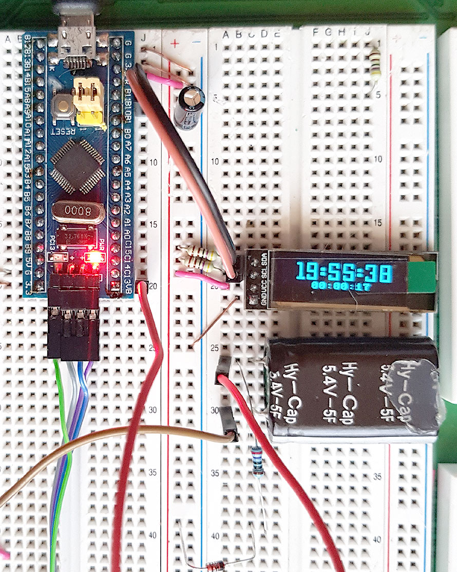
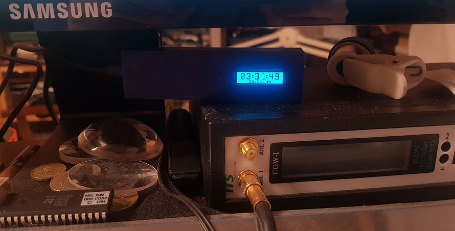
The logic of graphic chips is the same, but init sequence and commands may be different. Also, there are some options about the “glass” type, so there is no universal screen driver. Here is some screen collection connected to the same STM32F103 chip and using all the screens simultaneously.
LCD SPI I2C color screens gcc library for STM32F103 ARM bluepill
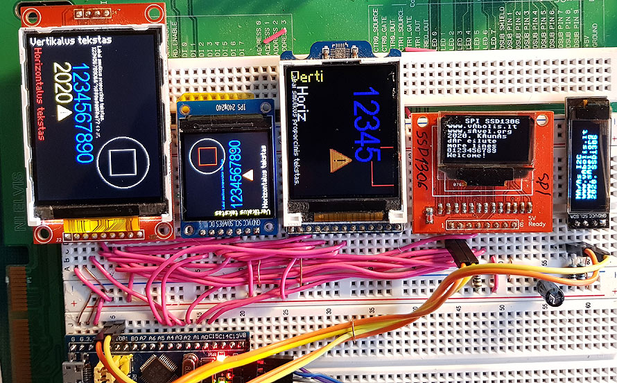
From left to right: ILI9341 (320 x 240), ST7789W (240 x 240), oldest ST7735R (160 x 128, other configurations optional), SSD1306 (128 x 64), SSD1306 (128 x 32, I2C).

Small screens do not have a full graphics library implemented (who needs to draw a circle on a 32 lines screen?). The font in the library has an error (lost small “A”).
Typically library can do:

  • Draw arbitrary pixel
  • Draw color data to rectangle: fill with color or image data (sprite)
  • Draw horizontal or vertical lines
  • Draw rectangle
  • Print text using fixed size font
  • Print text using proportional font with lame sizing (vertical or horizontal)
  • Print large proportional text (limited font data)
  • Do some hardware tricks: scroll, inverse, change intensity, flip image…

Many libraries use source code from the internet, but some errors are fixed and I added optimization for speed and size. Also, I introduced my errors too.

For example there is some simplification in source code. First line is from popular “programming language”, second is mine:

//was:
 for (pixels = 0; pixels < x1 - x0 ; pixels++) { ili9341_send_word(color); }
//now:
 for(x0=x0;x0<x1;x0++){ILI9341_send_word(color);}


We save one variable and useless calculations.

Other example. It is more important in speed optimization (for the screens it is very important):

//was, original:
 for(i=0;i < (w * h);i++)
 {
 c1 = *buffer++;
 c2 = *buffer++;
 ili9341_send_byte(c1);
 ili9341_send_byte(c2);
 }

//new:
 ILI9341_write_buffer(buffer, w*h*2);


Instead of sending thousand separated bytes, why not to use HAL library to send whole buffer using DMA or interrupt driven routine. Even sending buffer in blocking mode is much faster, than sending thousand of separate calls to procedure for just one byte of data.

There was problem in demo program- the function names for different screens used same variables and macros. In the real word program it is not the problem, because nobody use several different screens in the same project.

All source code for libraries, demo program for STM32F103 (bluepill), compiled binaries are included in archive.
Not all tricks are implemented in libraries- especially hardware scrolling and specific controller chip features.

Posted in Anything, MCU | Tagged , , | Leave a comment

ARM:0014 STM32CubeMX libraries for sensors and screens

In fact, any new program written for MCU is only copy-paste from older projects. Not real copy paste, but using the same libraries and subroutines. For some upcoming bigger project, I decided to use STM32 microcontroller, this means, I need to port several AVR libraries from older projects to the new ARM MCU. Due to historical reasons, older libraries were a bit chaotic. New versions are a bit improved, unified and much easier to use.

STM32CubeMX bluepill gcc libraries for sensors and various LCD screens
Porting somehow was very fast. Most of the problems were with the I2C bus- breadboard I used had some issues and I added additional termination resistors to keep everything stable. Maybe bigger capacitance of the breadboard or bad connections inside.

All sensors and screens are from China, only FM75 is from an old plasma TV set and MAX44007 donated by a friend. I had no idea what to create next and also I was a bit bored. And one day, I received a letter from them, with an offer to create some any project I wish and they will give some of the needed components. After this, I made a small poll about projects people need for now. I add some engineering touch to poll results and in a few posts I will start step by step articles about one smart thing.

Sensors and screens used in this test are:

  • LM75 temperature sensor, I2C (FM75 is advanced version, compatible with LM75)
  • MAX44007, I2C, digital calibrated light sensor.
  • PCF8574, I2C, 8bit I/O extender.
  • Old school txt LCD ekraniukas on PCF8574 extender. Free 5V – 3V level shifter.
  • SSD1306 OLED screen on I2C bus.
  • Analog input- not external module, but part of STM MCU chip.
  • RTC (real time clock)- also not external, but build in STM MCU.
  • BMP180 Atmospheric pressure sensor with temperature detection option.

Somehow I forgot to add DHT11 sensor code in this post. Sorry. I think in some future post it will be.
The OLED screen is using Commodore 64 font and there is error in font data. Will fix in future.

All libraries are compatible with GNU gcc and STM32CubeMX programs. All files compile without single warning.

Do download source code: OLED screen, sensors libraries compatible with STM32CubeMX and gcc. Compiled versions for STM32F103C8 (Bluepill PCB module).

Some data from sensors are shown on OLED and LCD screens and all data is sent using the USB virtual COM port for debug purposes.

Continued on Part 2.

Posted in Advert, Anything, MCU | Tagged , , | Leave a comment

ARM:0013 STM32CubeMX – USB HID keyboard

Now we will build a USB keyboard. This project is based on STM32CubeMX canned example, HID mouse (see previous article). But we will change mouse to keyboard. Both devices are from the same HID class. First we need to change the device descriptor. Descriptors are quite complex bunch of numbers with strict structure. For this example we will use another program and generate generic keyboard descriptor.

HID descriptor creator
This is a screenshot of a HID descriptor tool from www.usb.org.
Continue reading

Posted in Anything, MCU | Tagged , , , | Leave a comment