ATMEGA USB 007

I’ve already mentioned that I have small problems compiling Windows executable from source code. It is maybe my compiler’s problems. Maybe it is some strange version build or bad crack :). I was using Borlan Delphi Professional, Second Edition v7.2, Created 2006 by Lite Application.

After some experiments I managed to solve the problem is some strange way. It is just some workaround, not real problem solution. I am not Borland guru, but after I added some useless lines to source code the program is working fine. Description of changes are in source code and “readme.txt” file.

Here is modified USB-LCD software for windows with source code for Borland Delfi 7. It is working on my computer with WinXP Pro SP2, and P4HT hardware: 20071007.zip.

Posted in Anything | Leave a comment

23 inch screen

I’ve tested 23″ Apple Full HD wide cinema monitor. The difference in size compared to standard 17″ LCD monitor is not very big because width and height (aspect) ratio is different. For standard, old, LCD it is 4:3, while Apple monitor is 16:9. Width of monitor is measured in hypotenuse and the jump from 17 to 23 give us only ~1 inch gain in height (~7″ in width).

Full HD monitor

Native resolution of the monitor is 1920×1200 pixels. This is enough to display full HD 1080p standard images.

Full HD monitor

The resolutions enables to play HD movies in full resolution without any software tricks and resizing. The quality of the monitor is very good- not speaking about possibility of dead, stuck or hot pixels. Back-lit of the matrix is smooth and even. One very good feature used in Apple monitors is that all the wires are combined to one. So, USB, 1394 (firewire), video (DVI) and power lines are in one single chord. No more spaghetti on your desktop. There is USB and 1394 hub on monitor- no need to search empty slot to connect your USB flash disk, DV camera or 1394 hard disk.

Full HD monitor

Such big screens give us lots of space on the virtual desktop. We can place lots of icons and gadgets on the screen. The only problems is that when more icons on the screen, then more lag in the windows. Also, when there are hundreds of icons on the screen it is very difficult to find needed on. Wide screen is useful not only for HD movies, but in spreadsheet calculations or programing in MS Visual Studio. Especially in new versions- MS added many useless color borders in serious work software. I thing that Bill is still stuck in color crayon shop introducing WinXP and now he discovered aquarelle (water colour) department with his Vista windows. Working with Adobe products are fine too, but better is to use dual monitors for this.

Full HD monitor

There is small problems using big monitors in modern internet pages- there are many pages with static width design (my wordpress template is static too 🙂 ) and such web pages looks very ugly when opened in full screen mode on such devices.

There are lots of white space for notes in these web pages 🙂

Posted in Anything | Leave a comment

Cool resistors

I found very cool resistors in old equipment. They are very nice design. The values are almost unusable in our days, especially in hobbyist works, but resistors are very nice. Resistors are inside glass tubes. The resistance is very big- it was some timing selector in old scientific equipment.

The value are in quite strange line: 316.2MΩ. Yes! It is three hundred sixteen millions, two hundred thousand ohms. All other resistors are similar, it differs only in tens: 312.6, 31.62, 3.162M. Less the value, more precise resistors are. 3MΩ is 0.5%. Glass ones only 1%.

resistors

Resistors on other switch are: 316.2M+0.00068uF, 100M+0.0022uF, 31.6M+0.0068uF, 10M+0.022uF and etc.

resistors

The device itself was made using mixed technology. Mainly using discrete resistors, but high voltage part was made using electron tube. The print on the tube is: VICTOREEN 7234, CLEVELAND, MADE IN USA. Tube is made circa 1970. The tube was regularly checked as it is many handwritten numbers on it.

The tube is older than me 🙂

Posted in Anything | Leave a comment

Video over UTP

I installed video surveillance system at my work place. Nothing special 6 color CCTV cameras, one computer with few hundreds of gigs storing about a month of h.264 video. But I had a problem with one camera. The distance from camera to computer is not very big, about 300 meters (~900 feet). But the problem was that cable must pass several storage and manufacture workshops. With very electrically noisy environment. Also, the ground potential in the ends of cable is different. So, I decided to use already installed UTP cables. There are lots of commercial solutions to transport video over UTP cable. But my budget was very small, in fact I managed to empty it before this UTP problems… 🙂 I bought cheap, passive BNC to UTP video balloons. Connected… and it was great disappointment. Mine video baluns didn’t have galvanic isolation between UTP and coaxial cable. Also, the signal strength was very low and full of noise. This was my mistake- in fact, video balun is not simple 75 ohm to 100 ohm line transformer, but some auto-transformer. And the transformer rate is 1:1. don’t believe to all mystical distances adverted in balun description…

There were some problems to solve:
1. Galvanic isolation- to remove ground loop effect.
2. Convert asymmetrical coaxial cable to symmetrical and vice versa in wide frequency band. (50Hz…5MHz).
3. Cancel all possible interference from working devices in workshop.
4. Compensate loses in UTP cable.

The only solution is active amplifier. I selected old chip from Elantec (now Intersil) EL2044C (Low power, Low voltage, 120MHz Unity-Gain stable operational amplifier) from some video multiplexer. This chip is intended to use in video device, wide supply range (from 2.5V to 36V), output designed for 75 ohm video load.

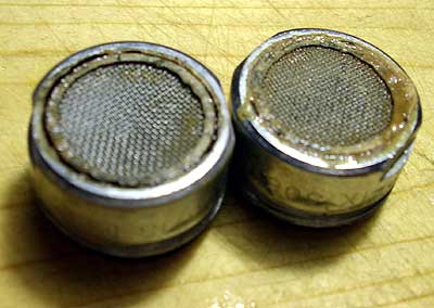
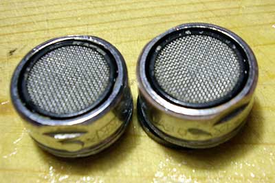
Most complicated part in this design is transformer. It must be very wide frequency range. In transmitter side I used passive solution- I used that video balun. It will convert to symmetrical signal video output from camera without any additional devices. On the receiver size I build small box with PSU and video amplifier. May problem is transformer specifications- all internet is full of “buy it” solutions and no “make yourself”. I don’t know how many windings must be in the transformer and what size or core to use. So I decided to use “connect and test” version. Using spare UTP cable I connected “line emulator”. I had about 120 meters of cable, so I connected all pairs in serial to get 4×120, about half of kilometer of signal cable. Video source- DVD player. On other side TV. First transformer I selected made bad results- it was possible sometimes to catch video, but now colors and lot’s of other problems like shades. I connected oscilloscope to the end of cable and revealed, that there are lots of reflections in cable and high frequency part of signal is lost in transformer. Color in PAL is transferred using 4.43MHz frequency and all this color component is very low. I added some capacitors to increase gain in higher frequency, but this didn’t solve the problem.
Suddenly, while browsing the internet, I found some web-page about one man using transformer from old LAN card to transmit 10MHz signal over symmetrical cable. I grabbed old LAN card and used transformer… The “color” situation was better, but I’ve lost low frequency part of the signal… The final solution was a bit crazy: dual transformer. One for high frequency and other for low. Both transformers connected in serial. Don’t mix phases in transformer.

Final circuit diagram (schematics) of the amplifier:

Video over UTP

Upper transformer is from LAN card. Lowe one is some from some power supply- it was feedback transformer on ferrite ring.
I don’t remember real value of the capacitors. 100 ohm resistor near transformer is main line load. Capacitor is used to increase high frequency gain. 500 ohm trimmer is used to adjust the reflections in the cable. Horizontal 100 ohm resistor is less that 100 ohm. I don’t remember (about 47Ω). Transformers are 1:1.

5 kΩ trimmer is to adjust gain.

PSU is double voltage, +6V and -6V, made from 12V with synthetic ground.

Posted in Anything | 1 Comment

CIS

At work, sometimes, we need to print some papers in color. So we need some cheap color printing solution. First we used old HP 970cxi printer, but now we need to print more. Original cartridges are very expensive, so we used refilled ones. It is very easy to fill color cartridge, just add some ink using top hole. There some more work with black ink cartridge- the hole must be closed with steel ball. But the cartridge is too small. So I bought more powerful printer for this- HP Business Ink Jet 1000 series. It is “semi- professional” printer with unmovable cartridges. The cartridges contains much more ink than moving ones. But I bought this printer having idea about CIS (continuous ink system). In some Russian site I even find instructions how to build it and how to disable ink cartridge chip. But then I decided to use already made solution and bought CIS system from China in eBay. For about $90 (including shipping and handling) I received full CIS system prefilled with ink. Here is the photo of CIS system in our printer:

CIS for HP1000

We already added ink to the system. Just pour some in to the bottle and that’s all! The only problem is with magenta color- some problems with ink head. I don’t know what is causing the problem: bad ink, bad pressure of ink, bad parking or just coincidence.

Posted in Anything | Leave a comment

Paypal in Lithuania

Original post dated September 28th, 2007.

After about ten years of waiting, most popular online payment system is working in Lithuania. Few years ago we used Western Union online payment system, but it was closed. Meanwhile Paypal was afraid of Lithuanian hackers or our bank system. Now, from 28th of September, the system is working. You may donate any sum to support this web log using this image link:

Thank you for your support!

Posted in Anything | 2 Comments

Cleaning tap filter

A bit offtopic, not very electronic post. Our tap water is full of lime (calcium). And this lime tens to grow on small tap filters, aerators. After some time I noticed, that the water stream is not very even, the bubbles are not so dense and small. After some more time the stream is skewed. The problem is very simple- lime on the filters. It is possible to find and buy new filters (aerators) in Aikada store (I often visit this company as I am responsible for IT in this company)… But coffee is better in Vitra company. 🙂 So, I visited shop and noticed, that some aerators are missing in display. After some interrogation they confessed, that some visitor steal those small devices. So, I decided to describe how to clean all lime using environment friendly way.

lime on aerators

This recipe is usable even with such large device as cloth washing machine.
Collect all aerators (filters), other small parts covered with lime. These parts must be thermal resistant. Put all parts to electric kettle, add some water and some citric acid. About two full spoons for cup of water. Switch kettle on…

cleaning lime

After few minutes the stench from kettle inform, that everything is going fine. After some time, the stench disappears, and the water will get yellow color. Now rinse the kettle.

lime gone

The same recipe for washing machine- just add about one or two kg or citric acid to it and start the “hottest” cleaning program. And no need for expensive special washing materials, no Calgon… Use your saved money for more pleasant purposes.

This article is a bit “advert” type.
Posted in Anything | 1 Comment

ATMEGA USB 006

It is time to use USB. After several unsuccessful experiments I found some working project in the internet. Maybe other project are working too, but only this one was usable and understandable for me. As I need not only binary compatibility, but compatibility in the source code level. I want to recompile all stuff by myself. In this project only USB Windows system drivers are downloaded from sourceforge web pages.
Why designing the PCB I looked to several other project and adapted my circuit diagram to accept several types of connections. With slight modifications, it is possible to use other firmware.

AVR USB LCD

So, the USB- Universal Serial Buss. This “universal” means that this system is multipurpose and more complicated. It is not only serial data transfer, but stack of procedures, drivers and other stuff to connect external devices to master unit using same buss. It is more complicated that old RS232 serial one and it is very hard to implement all features to simple device. Also, as this buss is “universal” globally, there are some limitations- every device must have unique identification. This identification is coordinated by some organization. This organization distributes VIN (vendor identification number) for money. We shall use free, testing numbers. All software is distributed under GPL/LGPL licenses, so fell free to use it. USB firmware is used from http://www.obdev.at/products/avrusb/index.html. VIN/PIN (also called VID/PID) is used from same source.

Also, LCD module is used to test this project.

There is small testing software for Windows to test the device. It allows to print text on the LCD and some other small command. The source code will be in the next post as I have problems with compiling it with my compiler.

20070922.zip.

Posted in Anything, MCU | Tagged , | 1 Comment

ATMEGA USB 005

There are lots of chips with serial control. Some of them use Philips I2C buss. There two data lines and two power lines to transmit all data. There DTMF encoders, switches, Dolby surround audio processors, multiplexers and many many other devices. Just open any TV set and you can find some- like TV tuner. ATMEL chip has build in serial interface, but it is called TWI. In my PCB there are two bigger SMD pads to connect I2C buss. Don’t forget to solder 10K pull up resistors.

FM75

For testing TWI bus I selected I2C temperature sensor. It is LM75 or any other clone. I am using small PCB from old plasma display panel with Fairchaild FM75 chip. It is smarter and more precise clone of original LM75. FM75 is backwards compatible with LM75. It has more precision and this means more data bytes available to read. At full precision it used 12 bits for temperature. In my software I used simplified algebra to convert 1/16 fractions to metric system. For more precise calculations, read FM75 and LM75 datasheet. And maybe AD7416 datasheet too.

FM75 ATMEGA16

I am using i2c.c from internet, from USB Tenki project. This project is very interesting, pay a visit to original Tenki web page for more advanced device. lm75.c is from same source. LCD modules are same as in older my web blog posts. When you connect your LM75 chip, don’t forget to check the device address- base address is the same, but user selected pins maybe connected in other way.

Programa: 20070919.zip.

With these chips and software example it is possible to build some thermostat project. But don’t write all controll stuff for ATMEL chip. Read the datasheet again and use LM75 thermostat option. Use ATMEGA only for control, display and setup.

Posted in Anything | Tagged , | Leave a comment

ATMEGA USB 004

There is ADC in ATMEGA16 with 8 multiplexed inputs. This analog to digital converter have several interesting options. Here is abstract from datasheet:

• 10-bit Resolution
• 0.5 LSB Integral Non-linearity
• ±2 LSB Absolute Accuracy
• 13 – 260 μs Conversion Time
• Up to 15 kSPS at Maximum Resolution
• 8 Multiplexed Single Ended Input Channels
• 7 Differential Input Channels
• 2 Differential Input Channels with Optional Gain of 10x and 200x(1)
• Optional Left adjustment for ADC Result Readout
• 0 – VCC ADC Input Voltage Range
• Selectable 2.56V ADC Reference Voltage
• Free Running or Single Conversion Mode
• ADC Start Conversion by Auto Triggering on Interrupt Sources
• Interrupt on ADC Conversion Complete
• Sleep Mode Noise Canceler

The ATmega16 features a 10-bit successive approximation ADC. The ADC is connected to an 8-channel Analog Multiplexer which allows 8 single-ended voltage inputs constructed from the pins of Port A. The single-ended voltage inputs refer to 0V (GND). The device also supports 16 differential voltage input combinations. Two of the differential inputs (ADC1, ADC0 and ADC3, ADC2) are equipped with a programmable gain stage, providing amplification steps of 0 dB (1x), 20 dB (10x), or 46 dB (200x) on the differential input voltage before the A/D conversion. Seven differential analog input channels share a common negative terminal (ADC1), while any other ADC input can be selected as the positive input terminal. If 1x or 10x gain is used, 8-bit resolution can be expected. If 200x gain is used, 7-bit resolution can be expected.
The ADC contains a Sample and Hold circuit which ensures that the input voltage to the ADC is held at a constant level during conversion. The ADC has a separate analog supply voltage pin, AVCC. AVCC must not differ more than ±0.3 V from VCC. Internal reference voltages of nominally 2.56V or AVCC are provided On-chip. The voltage reference may be externally decoupled at the AREF pin by a capacitor for better noise performance.

Software is very simple. It just read data from ADC and prints the results to LCD module. With small change in the source (just uncomment fre lines) and it is possible to read data from all channels.

ATMEGA ADC

Changing value near text “Stepas” just indicate the cycle number (in default program version) or ADC channel number. And if this number is changing, we can determine, that software is still working 🙂

Sorftware, source code: 20070918.zip.

Posted in Anything | Tagged , | 1 Comment