
(AI translated. Orginal article from 2022.06.15)
Antique LED Indicator, probably from some Soviet calculator. Its imperfection is charming:
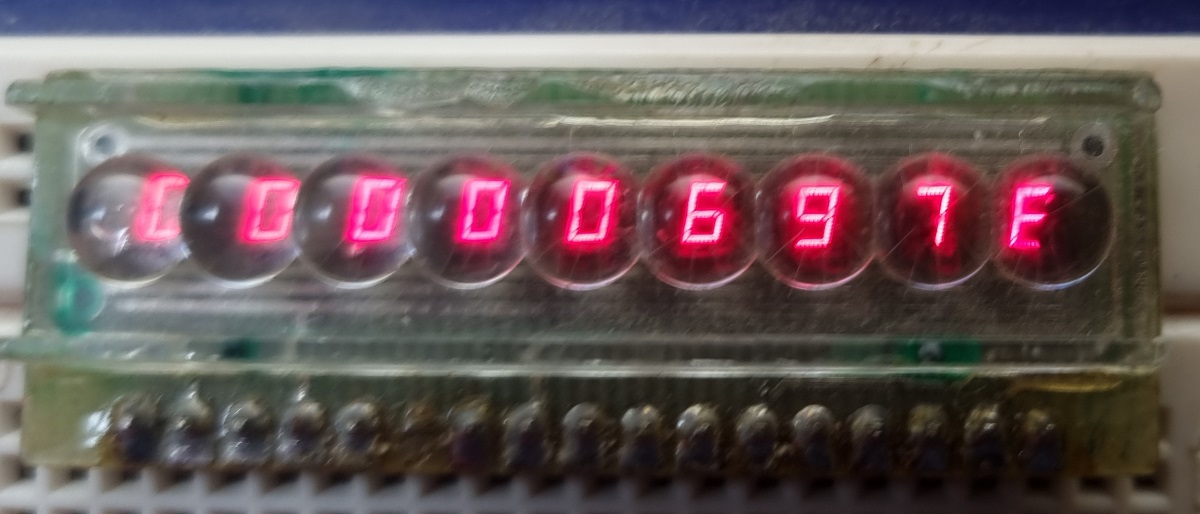
The symbols are tiny (hence the plastic lenses), the brightness is minimal (at saving currents). But it’s charming in its own way.
Such an indicator requires quite a lot of wiring and dynamic indication to connect. For the demonstration, I used a breadboard and a “bluepill” board (STM32F103C8t) – the microchip is small, almost all pins are used for the indicator. You need to attach some resistors to the anodes (positive electrodes) to limit the current through the LED, only 3mA in static mode per segment. When using dynamic indication, the allowed current is 40mA, but if the indication stops, it’s goodbye to the LEDs.
STM32F103 bluepill source code (StmCubeMX) and compiled hex.
Connection: PA0-PA7 (through resistors) LED segments, PB0, PB1, PB3-PB9 – cathodes (places of symbols).
To speed up the program’s work, write the whole byte to the pins:
uint32_t data = GPIOA -> ODR;
data &= 0xFF00;

//Bits 31:16 Reserved, must be kept at reset value.
//Bits 15:0 ODRy: Port output data (y= 0 .. 15)
//These bits can be read and written by software and can be accessed in Word mode only.
data |= font[a];

GPIOA -> ODR = data;
It is still a bit unclear whether to write/read 32 or 16 bits. I tried all the options, all work.
In another place:
uint32_t data = GPIOB -> ODR;
data |= 0b00000000000000000000001111111011;
GPIOB -> ODR = data;
Again, the same question: 16 or 32. Is it possible to optimize using GPIOx_BSRR? (port bit “reset/set” register)
GPIOB ->BSRR = 0b00000000000000000000001111111011;This option also works.
Clunky:
/* 74LS154 would be better */
if      (screen_pos==0) {  HAL_GPIO_WritePin(GPIOB, GPIO_PIN_9, GPIO_PIN_RESET); }
else if (screen_pos==1) {  HAL_GPIO_WritePin(GPIOB, GPIO_PIN_8, GPIO_PIN_RESET); }
else if (screen_pos==2) {  HAL_GPIO_WritePin(GPIOB, GPIO_PIN_7, GPIO_PIN_RESET); }
else if (screen_pos==3) {  HAL_GPIO_WritePin(GPIOB, GPIO_PIN_6, GPIO_PIN_RESET); }
else if (screen_pos==4) {  HAL_GPIO_WritePin(GPIOB, GPIO_PIN_5, GPIO_PIN_RESET); }
else if (screen_pos==5) {  HAL_GPIO_WritePin(GPIOB, GPIO_PIN_4, GPIO_PIN_RESET); }
else if (screen_pos==6) {  HAL_GPIO_WritePin(GPIOB, GPIO_PIN_3, GPIO_PIN_RESET); }
else if (screen_pos==7) {  HAL_GPIO_WritePin(GPIOB, GPIO_PIN_1, GPIO_PIN_RESET); }
else if (screen_pos==8) {  HAL_GPIO_WritePin(GPIOB, GPIO_PIN_0, GPIO_PIN_RESET); }
It can also be optimized. But does anyone optimize anything these days?
Well…. how about this option:
unsigned int bits[]={512, 256, 128, 64, 32, 16, 8, 2, 1};

GPIOB -> BSRR = (bits[screen_pos] << 16);

or:

GPIOB -> BRR = (bits[screen_pos]);
To save MCU pins, you can use the 74LS154 decoding chip (К155ИД3). Then instead of 9 pins, about 4 would be enough.
The demonstration program counts a 32-bit variable, so the leftmost symbol definitely won’t change. And waiting for other symbols can get boring.
That’s it.
(optimization experiments not included in the archive)