PWM transformer are wounded like ordinary transformers. But there are some important differences. As the working frequency of the transformer are much higher than ordinary line transformer, the windings contains much less turns. Also, skin effect is introduced. Also there is some effect with magnetic flux. The simplified description is that the flux tends to stick to core. So all the windings must be as close as possible to core. Engineer must select the core that all the windings fills the core window.
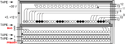
There few simple rules when winding the transformer. Keep highest current winding nearer to center core. Keep all winding interleaved across the bobbin width to optimize coupling with the primary winding.
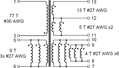
Example transformer: 4 windings = 5V, 5 windings = 7V, so 4+5 = 12V.

Since so few turns are involved in these outputs, it is usual for multiple parallel wire strands to be used on each output winding, and for the 5 V and 7 V outputs to be constructed as separate windings. This means, that sometimes you need to start even 8 wires at once.

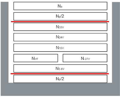
To make coupling between primary and secondary (-ies) better, especially when it is impossible to place all secondaries in one layer, it is possible to split primary.

Np-primary, Na-BIAS.
Red lines in the picture indicates wrapped insulation of Polyester Tape, 3 layers. Ordinary tape sold in local stationer’s (office) shop is not good. The tape must be thermal-proof. Original tape used in transformers can withstand even hot iron touch.

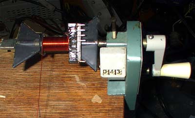
And here is some old manual winding machinery. And one half of primary are already done.
