Alternative output connection.
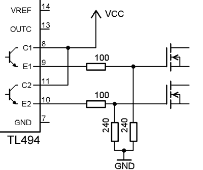
In other post I used classic output connection- collector load. Browsing in the internet I found Russian schematics of electric shock gun. It is based on the TL494 chip. But the output was connected in different way- using emitters while collectors were connected to Vcc. Here is the part of the schematics:

On the testing board everything is working. Quite cool, as we can eliminate one or two transistors- not need to invert signal to mosfet. Why this type of schematics is not in datasheet? … On original Texas Instruments there is NO such connection. But on ON Semiconductors same device (but with much more bigger values on maximum ratings) datasheet this is the first schematics! So, RTFM twice 🙂

HI. GREAT you website!!! I like much tha tl494 tutorial. look in my webpage. I am doing one eprom programmes hehehe, and looking for DC-DC with tl494, and find your! I use many resources from web, to make on dc-dc, but i found just with tl479, that is hard to find here, so i decide use the tl494. na dfound your website as one great place! tha everything works! i get from 5V to 40V. Thanks!
NICE tutorial. I have spent the last few days puzzling over the official Texas Instruments tutorials and I have to say, they really need a nice basic tutorial for engineering students like me! This is exactly what I needed, THANKS!
It is also interesting that you have found a really effective and simple typical app that TI does not mention at all. Again, they really need to use their imaginations a bit more when they are producing their (huge) documentation.
Totally nice and easy description. Looking more into to your site to see if you reveal more goodies 🙂 I am currently building a TL494 as a step-down with other options as well, such as step-up and push-pull stuff. Certainly beats using linear regulators to adjust power supplies 😛 The final unit will power several camera off flashes from a small 12volt battery. Thanks for publishing your workz!
I checked this circuit out. The output was under 200ma…just enough to power a 12volt pc fan but not enough to power a small 6volt incandescent globe. While the outputs from here were being pulse width modulated and variable while changing Rt and Ct, I could not increase amperage to a desirable level of about 500-1000ma. Even running in parallel did not help in increasing amps to a usable level. Any thoughts? I like this idea for voltage output as it is simple, but need some decent amps!! Maybe you might provide a portion of the schematic for me that the Russians used to make their version workable?
Part of russian circuit- is Here and Here, but I abandoned this circuit because it is lame. The upper mosfets are working in bad conditions. And they are dead in few minutes. Here is some testings.
About russian circuit of electric stun gun.
The first stage in making ~100…200V of DC. Next stage is simple pulsed transformer with output voltages up to 50000V. (low current).
The real, powerfull circuit is looking like this Big and real stuff. It is not mine invention. It is reverse engineering.

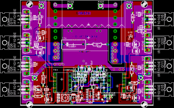
And here is a peek to PCB:
Thanks for that mate…my aim in using the tl494 is as a lossless stepdown dc-dc converter using a small lead acid battery to power portable 6 volt camera flashes. The amperage consumption during the first few seconds of powering the flash capacitor means for me that linear regulators are out…Way to much energy lost through heat, not to mention the impractical size of the heat sink 😉
Don’t invent bycycle. Use typical step-down pulsed regulator: LM2676, LT1076, etc.
Nice,…
Tl494 is really a magic chip
Thanks a lot, i loved it