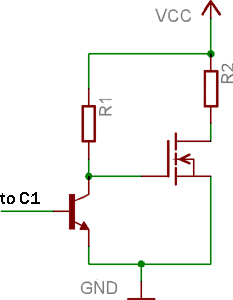
the output of TL494 is quite weak, and we want more power. So we need some powerful transistors attached. The most easy to use (and very easy to get- from old computer motherboards) are n-channel power mosfets. We must invert output of the TL494 because if we connect n-channel mosfet to output, in shut-down stage mosfet will be open and lots of current will pass threw then in DC. This may burn everything here… Also all PWM (pulse width modulation) will be inversed! So get generic npn transistor and connect according this schematics:

Output stage with power mosfet and passive drive.
The powerful mosfet is driven in passive on mode. It is not very good, but for testing purposes and low power are useful. R1 in the schematics are npn transistor load. Select it according max current the transistor can handle. R2 is the load of our power stage. In next experiments it will be replaced with transformer coil.
Now, let’s look at real oscillograms…

Sawtooth signal on the CT pin.

Soft start animation. Oscilloscope is connected to C1, TL494 output pin.

Soft start animation. Oscilloscope is connected to the drain of power mosfet.

Pingback: Savel brain dump in English! » Blog Archive » TL494 - magic chip, Part 2
Another joke, no power very hot only 50% efficient.
Schematics are working and fully tested. How do you think I’ve get osciloscope pictures?
50hz frec. shows on you display
Kevykev38… where did you find 50Hz? O just comment for link?
Great tuto! I deeply appreciate what you did!
Greetings from Venezuela.
Brother,, Can you please tell me why we need to invert the output for driving mosfets how things will get burned during shutdown period when there will be no any power available ?
When PWM if off, output is high (internal transistor is off). When output is high, external n-channel mosfet will open and pass current. It is bad. So if we invert output (or connect in emiter path) when PWM is 0% external n-mosfet is off, and when PWM 100%, expternal mosfet is on. It is “proper” regulation.