
Next tutorial- interrupts, keyboard (PS2 input) and USB COM port.
I have a small keyboard in my stash. It was from some flop device made by Amstrad. This keyboard has a 4 pin connector and I had hoped that it would be the USB. But after examining, I found it is PS2 only. Good stuff for the tutorial.
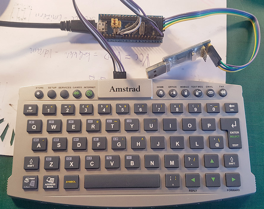
First we will do the PS2 interface and simply connect this keyboard to a virtual COM port via USB. It is possible to build a direct PS2-USB HID keyboard connection, but this is only a tutorial and we shall do it step by step.
We will use the same canned ST32CubeMX project for USB CDC (virtual serial port) example to communicate with the computer.
 PS/2 keyboard is using a special protocol, a bit similar to serial peripheral interface (SPI), but with some specifics- parity control and selecting direction of data transfer by grabbing the clock line.
First I detected pin-out of the cable- ground plane was connected to one pin, two pins have some same resistance to GND and only the one pin was different- this pin is for the power (Vcc). I connected the oscilloscope and found classical PS2 data and clock stream: synchronous data transfer- the data line is checked on the falling edge of the clock line (HL). The easiest way to detect an event on some edge of the clock, is using edge interrupt.
In the current CDC example, two pins used for keyboard interface- PA9 and PA10. Rename it to PS2_CLK and PS_DATA respectively. The data pin is just for input, meanwhile the clock pin is “GPIO_EXTI” (in this case “GPIO_EXTI9”). This pin is in “grouped interrupt” mode, so our generated INT/IRQ is called “9:5”. For the other pins, the names of the interrupts will change, but software will be the same.
Project GPIO settings windows are like this:
“Falling edge” interrupt and user labels.
Interrput settings or NVIC mode and configuration:
Do not forget to select the EXTI line interrupts.
Generate code, look at “Src” folder for “stm32f1xx_it.c” file- it is main interrupt handling file. Please download available source code from the bottom of the page for editing. It is a bit too much text to enter, so better download files and edit or just look at them.
First, add user includes- USB_CDC device and PS/2 scancode table. Keyboards use scancodes and do not send ASCII symbols to the computer.
/* USER CODE BEGIN Includes */
 #include "usbd_cdc_if.h"
 #include "PS2/PS2Keyboard.h"
/* USER CODE END Includes */
Configuring EXTI interrupts on 9-5 pins:
/**
 * @brief This function handles EXTI line[9:5] interrupts.
 */
void EXTI9_5_IRQHandler(void)
 {
 /* USER CODE BEGIN EXTI9_5_IRQn 0 */
 /* USER CODE END EXTI9_5_IRQn 0 */
   HAL_GPIO_EXTI_IRQHandler(GPIO_PIN_9);
 /* USER CODE BEGIN EXTI9_5_IRQn 1 */
 /* USER CODE END EXTI9_5_IRQn 1 */
 }

/* USER CODE BEGIN 1 */
void HAL_GPIO_EXTI_Callback(uint16_t GPIO_Pin)
 {
 switch(GPIO_Pin)
 {
............
case GPIO_PIN_9:
 ps2interrupt();
 HAL_GPIO_TogglePin(LED_GPIO_Port, LED_Pin);
 break;
 }
 }
/* USER CODE END Includes */
All this code is generated by the STM32CubeMX program, we just add a few lines and write a call back function “HAL_GPIO_EXTI_Callback(…)”. This function will serve all pin EXTI interrupts. I used the “switch-case” version just for fun and future expansions. This function must be kept as short as possible and serve only needed interrupts. Also, do not start any “big” process here- like sending data to the USB port. Keep it short!
After posting this article, I made small changes in the future revisions of the software and added PIN data handling directly:
Was “ps2interrupt()” , now it is “ps2interrupt(HAL_GPIO_ReadPin(PS2_DATA_GPIO_Port, PS2_DATA_Pin))“. After this change, my PS2 procedures do not use ANY hardware variables.
In main program (“main.c”) add:
/* USER CODE BEGIN WHILE */
while (1)
 {
   scancode=get_PS2scan_code();
   if (scancode !=0) {
   if(scancode==0xF0)
     { passcode=1;}
   else
     {
      if(passcode==1)
      {passcode=0;}
      else
      {
       c[0]=scan_decode(scancode);
       CDC_Transmit_FS((unsigned char *)c, 1);
      }
     }
 }
/* USER CODE END WHILE */
........
I am using a specific keyboard and it has a bit different logic inside. There are problems with modifiers keys (control, shift, alt) and there is a “released key” command. My short code just removes the key release commands and converts data from scancodes to plain ASCII. Feel free to change the conversion table to adapt for your real keyboard.
All source code, compiled binaries for the bluepill PCB are here.