
Blinking LED is not very cool. And not very informative. But we can use LCD module. It is very cheap and available device. There are many types of LCD modules in the world. I am using most popular- HD44780 controller based alphanumerical module. It is 2 lines, 16 symbols. There are 14 or 16 pins on this module. Two extra pins are used for backlight. All other pins are used in 8 bit mode. As MCU pins can be used for more usefull purposes, we use 4 bit mode- every byte is transfered in two cycles. As MCU is very fast, we can not notice any lag here.
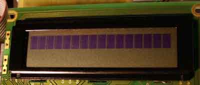
LCd module has selftest mode. When we connect power supply we must see upper line in black. If, not black square are here, try to adjust contrast using the only available trimmer on the PCB.
LCD control software is from internet. After several experiment I selected Peter Fleury program. Other versions I tested had some hardware limitations. LCD connection is described in lcd.h file. No need to change lcd.cfile. But you can peek to it to find what procedures are in here.
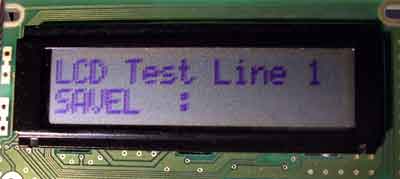
Testing program is in test_lcd.c file. There is some push button routines here too. I am using jumper named “firmware” as button.
If you power this device from computer’s USB slot, don’t pay attention to windows messages about unknown device connected to USB buss. We solve this problem later.
Software source and hex file for testing is here: 20070917.zip.