
Today we’ll open quite big Logitech Z-640 sound system sub-woofer. According the specifications:
- Total output power: 70 Watts RMS
- Subwoofer power output: 25 Watts RMS
- Satellite speaker power output: 45 Watts RMS (9 Watts RMS per channel)
- Total peak power: 140 watts
- System frequency response: 35Hz – 20kHz
- Signal-to-noise ratio: >75 dB
- Input impedance: > 5,000 ohms
- Shielded satellites for use near video monitors
Sold locally for about 250…300Ltl.
I am interested only in subwoofer, so satellite speaker are not analyzed. I am interested in subwoofer and audio amplifier. And it looks so cool…
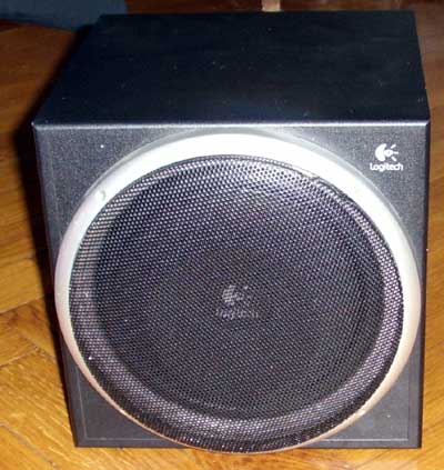
So, grab your screwdriver and tear it apart…
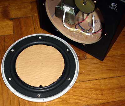
I removed protective grid and unscrewed all screws in front and … removed big passive membrane. It is not a speaker! Inside you can see smaller speaker and small transformer. It is impossible to remove back cover without opening the front as wires inside the box are very short.
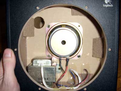
That small hole near transformer and speaker is tunnel of phase inverter. It is going to amplifier side of the box.
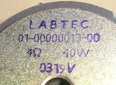
If you can believe in Chinese made prints, the speaker is more powerful than printed in technical specifications. But it is Chinese made stuff, using special, Chinese “watts”.
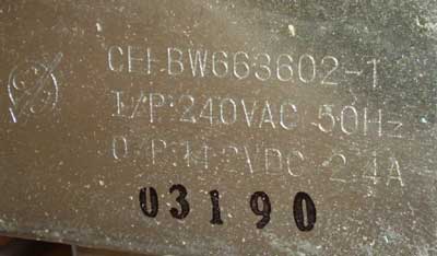
The transformer for audio amp PSU is too small. Primary is 240V, secondary only 14.2V at 2.4A max. According to simple calculations- P=U*I=14.2V*2.4A=34.08W PSU output (compare to description of total power of 75W). And take note, that amplifier is not 100% efficient, and there is not always 14V in output. So, you can’t drain more power from audio amplifier than it received from power supply.
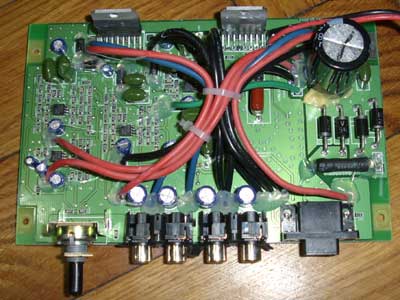
The audio amp itself is made using two TDA7375A chips. According to the data-sheet, it is: 2 x 26W/4Ω @14.4V, 1KHz, 10% or 4 x 7W/4Ω @14.4V,1KHz, 10% or 4 x 12W/2Ω @14.4V, 1KHz, 10%. I don’t like this 10% THD at max power. So for normal music, do not use max power.
According to the PCB, one chip is connected as four independent channels and other chip is connected as dual bridge- one bridge for subwoofer and one for front speaker. As the speakers resistance is not 2 ohms, the output power is less. Also, the output capacitors are too small. According datasheet you must use 2200mkf and in real, only 470mkf caps are used. So less power is transferred here. Chip max output is 7W and is speaker system specifications- 9W. This is lie.
There are some positive things in this audio amplifier. The OCB quality is very good. All possible moving parts are glued to PCB- no annoying sound in subwoofer. All screws are covered with varnish- so they will not unscrew by themselves. In fact, it is very difficult to unscrew the screws. All resistors on the PCB are precise- I didn’t found any “approximate”, 10% resistors.
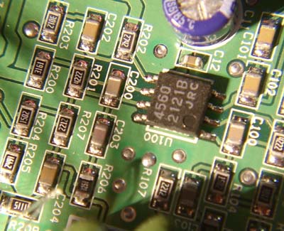
Preamp is made using quite good S4560 operational amplifiers. According the datasheet it is linear up to 100kHz. So the sound will be clear, without distortions.
If the PSU was bigger, the capacitors value proper and output chip better, it could be very nice amplifier. Now it is quite good device if playing music not too loud.
I am currently soldering/wiring the d-sub connector back onto a z640 vga cable but can’t get the 15 pin colors correct. Would you have any knowledge of this?
u stuipid chinky u cant even talk proper english and you bag some old logitech system for being chinese…… dont u lyk things from your own country?
austin’s comment is typical: claiming about my bad english (it is not my native language) while his writing is much worst.
All logitech stuff is made in China. But this model is especially bullshitting users.
BTW, look at the post date. It is January of 2007….
How did you remove the protective grid?
It was 4 years ago… I think I pull out the grid, it is not glued.
It’s great to see you monitor your posting after so long.
I’m about to open my Z-640 to see if i can find a replacement speaker ’cause from the way it sounds I think the speaker coil is displaced. ( that thump you get that’s not music).
From the pics the magnet size looks much bigger than any other 4ohm 40 watt speaker i’ve seen before – for that diameter cone.
If i can’t find a replacement, what range of ohm/wattage do you think will work?
Thanks
It is written on the speaker- 4 ohm, 40W. So- any normal speaker, with 4 ohm coil. Better low freq ones, as it is subwoofer. BTW, I was not using this device, I just dissasembled it and throw away 🙂
If the transformer delivers 14.2V on the secondaries, it will be much higher after the rectifier diodes and capacitors. You have to multiply it by the square root of 2 (approx 1.41) and then subtract 2x 0.6V for the diodes. So you would end up with (approximately) 18.8V on the amplifier PSU rails.
Who cares about √2 increase when it is only few wats, not HUNDREDS.
Also, if I could measure voltage with load on this transformer, I will never get 14V. It is typical china bullshit for western people. Who ever made selfmade transformer would tell what is the size of core for such power.
Hold your horses. I’m not saying Logitech’s specs are correct, and it may still be “china bullshit”. I don’t know, nor do I claim to. I simply pointed out your calculation is in error. And it is. True enough, you probably won’t get 18.8V when under load. But then, why didn’t you measure it? A simple multimeter would have done.
I never actually made a transformer myself, but I made a class-A amplifier a few years ago, with a 2x 25V transformer and probably around 0,2F total capacitance.
Btw, you say that the speaker is more powerful than printed in technical specifications. Speakers aren’t “powerful”, they just have a maximum power rating they can handle. For this speaker, it’s apparently 40 watts. The technical specifications specify the amp’s output power (or at least they should), not the speakers’ maximum power rating.
It is simple: Pspeaker>Pamp, and Ppsu>Pamp. Thats all. There may be translation problems, that in Soviet Union there was good parameter for all devices: nominal power (номинальная мошность). This means maximum power this device can withstand without damage and with specified quality for infinity of time. No bullshit like max power, RMS power and etc.
Also, I am calculating power of transformer. Not the amplifier. Amp power is from datasheet. I don’t need to multiply by square root of two to calculate power of transformer.
The basics of amplifier design isn’t your strongest point!
In no way does the power used at the mains input reflect what will be available at the output!!!!!
… amplifier design can not negate basic laws of physics. Especially, first law of thermodynamics.
Thank you. I was looking at buying a Z-640 off craigslist. “BTW, I was not using this device, I just dissasembled it and throw away :)” tells me everything I needed to know.
Thank you. Having learned a second language, I understand the balls it takes to publicly post in a second language you are not totally fluent with. I invite those folks having problems with your English to make a useful blog and post in Russian.
And to those unable to understand the difference between Lithuanian and Chineese, go fuck yourselves, ignoramuses. He’s in Lithuania, posting useful information in YOUR language, not his. He certainly isn’t doing this for his own benefit. Or his family, neighbors or friends, who are even less likely to understand this than Russian. So, once again: GFY.
Hi, I have found your post and thought that you might be able to help me.
I am trying to use only the subwoofer with an input from a pre-amplified signal. The problems I have found are:
1) I don’t know what pin from the centre speaker is powering it on and off.
2) I don’t know what pin is used for the subwoofer pre-amp. I would need to use that one as my input from the decoder.
Could anyone help me, please?
It would be very useful to find the schematics, but unfortunately I have not been lucky enough.
Regards.
I bought one of these on craigslist, without the 5 speakers. I was pretty upset when the vga to rca cable that I bought didn’t work with it. I’m having similar problems as Campu. I now plan to just tear it apart and hook up my own amplifier to the sub itself and throw out the original amp. But I’m a little confused with the voice coil being separate from the actual speaker or ‘passive membrane’.
It would be very helpful if somebody could tell me how to use the vga input so I don’t have to buy another amp.
PS- I didn’t notice that your not as good at English, you seem to speak it quite well. You also sound like a pretty smart guy and thanks for the post!
it is not 15 pin VGA connector. It is proprietary connector to main control module. Without this module this device is about to be useless.
Does anyone have the VGA 15 connector pinout? All I got is the subwoofer, and I’m trying to revive it. I checked the +6 VDC on pin 15 and +15VDC on 8. Which pins should I connect to switch it on?
I don’t remember, but I think there is silkscreen print on PCB where all pins are described.
Just open the box, remove PCB (lots of screws and you need to unscrew the power chips.) and there is little daughter board (in some models) or direct print on PCB.
My system is giving me some problems…all speakers are working except for the sub…can anyone please assist me with this problem?? thanks
Dear Nevin, I think your system is damaged 🙂
HI,
I managed to figure out the pinout for the sub woofer. I managed to turn on externally and working. Any one interested to know the pinout ? Still there are three input pins that I need to understand but not that urgent my primary goal to get sub woofer running is completed.
pcg
Nevin.
Probably the fuse is gone. There are two fuses for the transformer primary and secondary sides inside the sub. IF all other things are working except sub, may need to check the sub speaker.
thanks,
Pubudu
pcg: I’d like to know the pinout, found the old sub laying around and I’ve probably thrown the satellites years ago. It would be great if I could use it as a sub for my TV as the TV-speakers doesn’t pack much punch. I actually found the post searching for the pinout.
The post is 7 years old. I don’t have this item anymore.
Especially, this device is pile of crap.
Why you are saying it is pile of crap? I still own a Z-540 and Z-640(i bought it used from ebay), the only problem i got is with the 640.
The Same 640 you own, but Europe version, i can say the Transformer is bigger then yours (i guess it is a new rev.) but it has a loud noise, which is annyoing, any idea how to fix it? Can i extend it to another case?
Sorry, this article is about 10 years old. I don’t have any Logitech products- Now I am using real hi-fi equipment.
What is “loud noise”? 🙂 You can hear mains buzz in output? It could be just dead capacitors (typical problem is that era electronics and the age).
Hey Thank you for your reply!
I can not efford real hi-fi and i like the Logitech Soundsystem, it does not have these hightones new Logitech Equipment got (and here you can say, the new Soundsystems are crap, they get damaged after warranty and the sound is not so good).
Anyway, it sounds like a gentle/quiet refrigerator when the compressor is working, hard to describe. you know these high voltage rooms? it sounds like that.
I opened the case (thanks to your Site, i know where to start, it is not the outside ring, it is the Metalmesh) and turn only the powercalbe in and the Transformer was starting giving the noise.
I have no problem with the soundsystem, but it can be mocking if im just surfing.
Hmm, maybe i just buy a poweradapter to switch the soundsystem off and on…
I found out that the Speaker from the Logitech S120 are perfect to replace any Speaker from the Z-640, 4 Ohm and 5 Watts, the original ones have 4 Ohm and 6 Watts, if someone want to replace them.
Anyway, what Hi-fi did you bought? 🙂
Any surround system? Or 2.1?
I’m interested and in need of the pin-out specs for the z640 system please. I don’t have the center speaker. Your help is appreciated, thank you.
Hello everybody still reading this post. Original post (http://www.vabolis.lt/2006/12/31/logitech-z-640/) was posted in late 2006. Now it is 2019. And the post was about how crappy this device is.
I don’t have any information about this device. I do not have this device (I trashed it after I wrote post).
Sorry boys and girls- it is ancient history.
Greetings from Vermont!
Logitech z640 VGA pin layout
Pin numbering is from left to right starting at the top wide side through the bottom narrow side.
1 is rear right analog input
2 is rear left analog input
4 is front right analog input
5 is front left analog input
6 is ground
7 is ground
8 is +17v
9 is ground
11 is +6v
15 is ground
To use the device without the pilot panel simply connect pin 14 to pin 11
Feed the analog signal to any input pin and it will get amplified in the corresponding analog output RCA jack and the bass will show up on the subwoofer.
Bree DaCosta
Bree, thank you for the information!
What is pin 14? You don’t have it labeled on your list.
Pin 8 does not need to be connected?
I love this thread… look at dates. Are somebody still using this stuff?
I want to buy logitech z 640 subwoofer circuit
All I wanted is the schematic for the control that plug into the back of the system.
I finally found who talk about this pin. I have smashed out the d-sub connector.
I hope is useful.
https://www.dropbox.com/sh/3zja8kd54atavf9/AAD3GAWZoVcAexBvEny6yUaSa?dl=0
How i can see what is ground or what is for example 17v ?
I tried to restore this sub but center speaker doesn’t turn on. Can anyone help me ?
Thank you!
Bree Da Costa can you explain me what pin i should to connect ?
Hello, I hope that the boy: austin on October 5, 2010 at 5:39 am, complains about my English, since it is not mine, I am translating my Spanish.
As you can see the date, it is a bit far, but I thank the administrator of this post, I got some valuable information from Bree DaCosta: July 29, 2019 at 8:42 am; for giving the information I was hoping to find and thanks to Campu: December 8, 2012 at 9:21 pm, for asking the question you hope to see in the post; for that reason now I can revive a card from a Z-640 and break the windows of my house with the Subwoofer ..
Thank you all for keeping this post alive for so many years and blessings to all equally.
Regards from Dominican Republic.
I am Jared.
Thank you Bree DaCosta!!!! I also couldn’t find anything anywhere to help on this Z-640 Logitech. I appreciate your help on this. Thanks again.
I will add my thanks to the list! I found one of these on the side of the road and have it up and running as a sub to provide a bit of bass for an old mini-system. Not the most hifi solution, but certainly helps. The information here was very useful.
Sir I need Logitech 211747-0000-A7
board
Thanks this worked but no volume control
Bree DaCosta says:
July 29, 2019 at 8:42 am
Greetings from Vermont!
Logitech z640 VGA pin layout
Pin numbering is from left to right starting at the top wide side through the bottom narrow side.
1 is rear right analog input
2 is rear left analog input
4 is front right analog input
5 is front left analog input
6 is ground
7 is ground
8 is +17v
9 is ground
11 is +6v
15 is ground
To use the device without the pilot panel simply connect pin 14 to pin 11
Feed the analog signal to any input pin and it will get amplified in the corresponding analog output RCA jack and the bass will show up on the subwoofer.
Bree DaCosta