
My old linear Li-ion charger somehow blowed up. I found small hole in the chip. As my all batteries were exhausted, I need to build new charger. I voted for new technology- switching charger for Texas Instruments. I selected BQ24103 chip as it is stand alone 1 and 2 cells charger. Here is the abstract from original datasheet:
SYNCHRONOUS SWITCHMODE, LI-ION AND LI-POLYMER CHARGE-MANAGEMENT
IC WITH INTEGRATED POWER FETs (bqSWITCHERâ„¢)Ideal For Highly Efficient Charger Designs For Single-, Two- or Three-Cell Li-Ion and Li-Polymer Battery Packs.
Integrated Synchronous Fixed-Frequency PWM Controller Operating at 1.1 MHz With 0% to 100% Duty Cycle.
Integrated Power FETs For Up To 2-A Charge Rate…
In normal words, this means- simple, small, smart and very few components.
After some time I received the chip and was very disappointed. The 21-st. century technology is not very good for hobbyist. The package of the chip is “Quad Flatpack No-Lead (QFN)” with thermal pad. Translated- fucking small lead-less chip 4.5×3.5 mm size and 20 connections. The PCB pith must be 0.23mm and the distance between center of them is only 0.5mm.
I managed to build homemade PCB using simple photo-resist coated plate and old laser printer. There is small problem with mine, single sided PCB. According datasheet I need to place up to 6 thermal vias under the belly of the chip. Yeah. At home and using single side. This cause small problem described bellow.
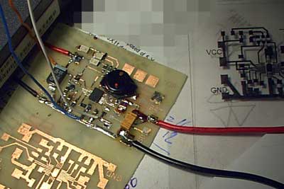
I prepared two PCBs at once as I didn’t believe that I’ll do it at first try. The size of the inductor is a bit big. But it is the first inductor I found in my spare box.
The chip must be soldered to PCB using hot air gun, but I don’t have one. So I soldered only the PCB and build small hill on center, thermal pad. I hope the solder melted under the chip while I was scratching around the chip with my 40/20W Weller. Only X-ray can prove it. The chip moved to side for 0.1mm, but the connections are all good (I hope) and I don’t want to re-solder it.
The circuit diagram is standard, from original datasheet:
I made these changes in circuit:
Shunt resistor is 0.22 ohm as I didn’t find 0.1 one in my scrap-box. So the max charge current is 0.7A instead of 1A.
I didn’t put the thermoresistor and around elements. I placed trimmer to set working conditions. Maybe in future I do it properly.
The PSU for charger must be from 5 to 16V. While using 15V power supply the chip is very hot due to the absence of thermal vias and proper cooling. So I am using 5V PSU when charging 1 cell battery.
All elements for this charger except the chip are second-use, salvaged from old ADSL modem, wireless router and SCSI hard disk.