
From time to time, in newsgroups, in www forums and in www pages, people speak about converting DC to DC, or DC to AC, charge-pumping, building inverters (step up, step down converters) for various devices. From high power car audio amp to handheld stazer. There are lots of schematics (especially in Russian web) using simple TTL logic, transistor and other devices. But why invent bicycle? There is special, very cheap and very easy to find, chip. It is TL494 (or any other analog). You can found it in any PC power supply. According data-sheet, TL494 is “PULSE-WIDTH-MODULATION CONTROL CIRCUIT”.
The TL494 incorporates all the functions required in the construction of a pulse-width-modulation (PWM) control
circuit on a single chip. Designed primarily for power-supply control, this device offers the flexibility to tailor the
power-supply control circuitry to a specific application.
The TL494 contains two error amplifiers, an on-chip adjustable oscillator, a dead-time control (DTC)
comparator, a pulse-steering control flip-flop, a 5-V, 5%-precision regulator, and output-control circuits.
The error amplifiers exhibit a common-mode voltage range from –0.3 V to VCC – 2 V. The dead-time control
comparator has a fixed offset that provides approximately 5% dead time. The on-chip oscillator can be bypassed
by terminating RT to the reference output and providing a sawtooth input to CT, or it can drive the common
circuits in synchronous multiple-rail power supplies.
The uncommitted output transistors provide either common-emitter or emitter-follower output capability. The
TL494 provides for push-pull or single-ended output operation, which can be selected through the
output-control function. The architecture of this device prohibits the possibility of either output being pulsed twice
during push-pull operation.
The TL494C is characterized for operation from 0°C to 70°C. The TL494I is characterized for operation from
–40°C to 85°C.
Before doing any useful device, I deeply recommend to examine how this chip works. This will be some sort of TL494 tutorial 🙂
Take your breadboard, prototyping board or anything you like and connect wires according this schematics:
TL494 test circuit
If everything is connected right and detail are similar to used in the picture, the schematics will be working. Leave 3 and 4 open. Use your oscilloscope to test is oscillator is working- on CT (pin 6) you must see saw. The output will be null. Now connect FEEDBACK (pin 3) and DTC (pin 4) to ground (GND). You must find square pulses on the output. In the next message I’ll explain the pins in more details.
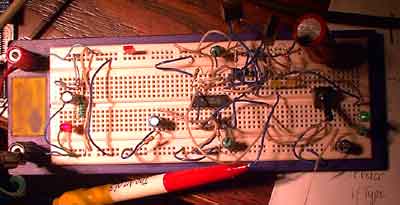
TL494 in the breadboard
Pingback: Savel brain dump in English! » Blog Archive » TL494- Power supply for VFD
Thank you very much for your interesting explanation. Quite a while ago I learnt to understand the TL494 by playing around with the circuits you proposed, although I didn’t use it to generate high voltage.
I finally built a PWM stepdown power supply (75V from solar cell to 12V), which is described (in German) on my homepage.
Max
hey…sir
m working with tl494…………..and have a test circuit shown in respected datasheet…
i want to know that how to get dead time between two output pulses for push-pull operation……… plz help me out…. thanks
Try to read datasheet… 🙂
The dead-time control input provides control of the minimum dead time (off time). The output of the
comparator inhibits switching transistors Q1 and Q2 when the voltage at the input is greater than the ramp
voltage of the oscillator (see Figure 28). An internal offset of 110 mV ensures a minimum dead time of
∼3% with the dead-time control input grounded. Applying a voltage to the dead-time control input can
impose additional dead time. This provides a linear control of the dead time from its minimum of 3% to
100% as the input voltage is varied from 0 V to 3.3 V, respectively. With full-range control, the output can
be controlled from external sources without disrupting the error amplifiers.
m not getting it….. i got the pulses but i want some time delay between on and off time of pulses…..
There is ALWAYS some dead time between pulses (when connected in push-pull mode). It is 3% off pulse width. If you need more, add some voltage to “dead time” pin (4). If you put here 3.3V or more, the dead time will be 100% this means no output at all.
Maybe you connected TL494 into “same output mode”. Show your circuit and what you get on osciloscope.
my circuit is same as shown by u………… i.e. test circuit……
but not getting the same pulses as shown in datasheet below test circuit………..
i have made two changes……. instead of using capacitance of value .01 microfarad (pin.5) i have use .1microfarad… and resistance of 47kohm…….(instead of 50k)… is this make any difference………..?????
sir
hello i am the member of joshi suraj…
please tell me ….in pin no 4 (dead time) we appled extra 3.3 Voltage in ic…..
sir when we connect the pin no 3 and 4 is grounded so the current is increase so what the problem…..plz tell me
If pin 4 is 3V or more then NO OUTPUT as deadtime is 100%.
Pin 3 is output of error comparator and input of feedback. Do not ground it. It is used only if error comparator is disabled. Or to provide negative feedback for error comparator.
Keep 3 float, 4 at 0 or less than 1V. Error comparator input according your needs and feedback.
hi, i managed to wire up the tl494 and got the output. but i’m doing a buck converter and wondering how do i have a voltage control mode from the output of the buck converter to the tl494.
is it through error amp 1, at pin 1 and 2?
thanks!
Sir,
I want to vary the both duty cycle and dead time. how can i do this. i want 30% duty and 2 us sec delay with 25kHz frequency.
For faye:
I’ve made buck converter with TL494, but it is not translated to English language:
http://www.vabolis.lt/2009/09/13/reguliuojamas-maitinimo-saltinis-nuo-5-iki-100v/
It is higher voltage version, but usable and convertable to other voltages. There is voltage and current feedback. The only problem is to select good inductor for very wide voltage range.
For ramesh:
I would like you to recommend some datasheet reading. I don’t want to calculate something for you.
I am having trouble with the test circuit. My circuit is exact. My duty cycle is at 97% and nothing I do will change it. I’ve set up a voltage divider off vcc to feed a signal into the feedback pin. I have also set a voltage divider off of the ref pin for the dtc. No matter the adjustments duty cycle is 97% or nothing.
Just measure voltage of ALL the pins of the chip and compare to datasheet.
how to get two successive on pulse separated with a space time
If I understood your question… no. This device is not designed for this. Use MCU maybe.
Is it possible to control the duty cycle of the signal produced by TL494 using MCU?
Instead of adjusting the duty cycle using potentiometer, can i use MCU to do the adjusting?
To Nads… yes is it possible. You need to use DAC on you MCU. But this will be a bit weird, because all new MCU have build in PWM…
Dear friend,
I am reading this article on your blog an i try it very interesting.
I have a problem with my 12vdc- 220vac inverter and so i started to read some articles about this ic pwm control.
My inverter have 2 tl494 (first and second stage), the first stage work (believe ok), but second stage not work.
Thank you
Kyu9971
You speak about something like this?
http://www.vabolis.lt/2015/03/01/dcac-keitikliai/
Is it worth your time to repair?
I am using the output control pin currently at Vref and connecting the emitters of both the transistors together to get a PWM regulated wave.
Sir,
How do I get complementary outputs from E1 and E2 so that i can drive a half bridge or class D inverter?
“Output Control” pin (13) selects output mode: Selects single-ended/parallel output or push-pull operation (half bridge/bridge).
When using emiter outputs, take note of voltage levels.
Thanks for reply.
i found this explain very interesting.
also with help of this i have repaired my inverter.
i have an question please.
is possibible to use an atx transformer (connected in reverse way) for realized an dc dc and un tl494?
bye kyu9971
hi, i tried to drive the dtc in pin 4 with potentiometre but at output i’ve only duty cycle from 50% to 99%, so how to get less ?
https://docs.google.com/file/d/0B8xT7Q4vaK-baUY2Z3U5S2FDNHc/edit?usp=docslist_api
In above schematic there are two pots one is 10k pot another one is 22k pot.
Can u please tell me which pot is for frequency and which pot is for duty cycle ?
In your picture everything is written! 22K pot is for frequency, so the word “Tuning ~350kHz” make some sense. Another pot, 10K one, is for duty cycle: “Adjust for 50/50 squarewave output”.
One reccomendation- do not use ancient designs for your SSTC, if you want to use TL494 you can, but do not use this crap driver circuit, especially 220ohm and mosfet inverter! 2W resistor? Are you crazy?
Check arround. It is 21st century! There are driver chips like TC4423, TC4424, TC4425, MAX15070 (for extreme drive), LTC4446, M63996FP, even optoisolated FOD3128 or A314J and zillions other.
If you want THE SAME with more stable design and less components see this:
HV PSU
Simple converter
Optoisolated mosfet driver
even some PSU with TL494 and IR2113 driver
If you do not have source for new chips, try to find bad plasma/LCD TVs, UPS, some drivers from automotive electronics. Even every computer motherboard have several mosfet driver chips. With very good driving capabilities at such high frequency. These ZTX transistor pair are very slow at Tesla coil speeds. I know, I tested your circuit…
Sorry,not all articles are translated.
Oh, wait… Is that complication for duplicate frequency? It would be simpler to use another IC, unless you have lots of 494s scrapped from ATX PSUs…
I do not understand Dave’s comment. Sorry.
I think I accidentally erased the first part of my comment.
It was after looking at the Richie Burnett’s Tesla Coil Driver. I said it seems weird (perhaps even ridiculous) to use a TL494, which has a pair of symmetrical outputs, wired in single ended mode and adding a trimpot to get a 50:50 ratio again and then add a phase inverter (VN10) to get again 2 symmetrical signals. Let’s leave this for the NE555!
That circuit makes no sense, unless he does that for frequency doubling and obtain 1 output pulse per clock cycle, avoiding the f/2 effect of the internal flip-flop, but is still a strange way to do it.
hi sir ,
i want to increase the width of pulses so what i have change so that i can consatantly change width
Hello
I have a charger works on tl494, the way to make the charger works continuously without stopping, and how I can take the maximum current, thank
Hi
What is the relationship between tl494 and lm358 charger permanently and continuously
Thank you
hi sir, i have a question.
the frequency of each two outputs is half the frequency of the sawtooth signal. is ok this?
thank you
andrea.
Sorry, I can’t catch yours mind. FYI Post is 12 years old… And original posting in Lithuanian language is even older.
thanks anyway
Sir is there a similar ic as tl494 but which can operate for more than 500khz. i want to work at 500khz switching frequency
I think it is. Now it is 21-st centyry and switching frequences sometimes are higher than 1MHz. Just check any company (not China) for switchmode PSU chips.
Thank you very much for your information. God bless you.