
I found LCD module (display) from Epson ECM-A0404. It looks like 20×2 module. Module has 16 pin connector… hmm… looks like standard LCD module.
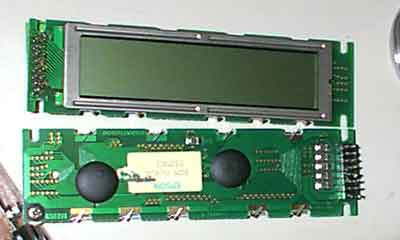
I connected wires according usual pin-out. But, oops!, some sort of short circuit. At first glance, it looks like, that pin 1 and 2 are swapped. Reconnected wires and nothing… Took another module- it has small left-out of old PCB. It looks 2 and 3 connected to GND. And 1 maybe is Vcc (Power). Rewired again- nothing. Maybe I damaged module, switched module and again nothing.
For testing purposes connected standard LCD module (16×2) … and it works.
This is Win-Amp plug-in working on Windows XP and WinAmp5.08e. This means, that EPSON module is using some non standard pin-out. Short search in interned didn’t help. Only few people searching for pin-out of this LCD module.
If you have a pin-out of tjhis module,please,send me via e-mail (max136@rambler.ru).Thank you.
I didn’t found any pinout for these module. I put it into “long” drawer… 🙂
1.)Epson ECM-A0404 from Canon fax
1 = Vcc
2 = GND
3 = ?
4 = contrast resistor
5 = ?
6 = ?
7 = ?
8 = ?
9 = D1
10 = D0
11 = D3
12 = D2
13 = D5
14 = D4
15 = D7
16 = D6
Tryed pin combinations but I’m still unable to get it to works…
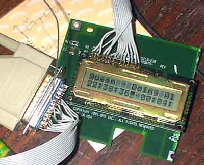
2.)Epson ECM-A0421 from Canon fax
14 pins, pinout compatible, initialization sequence different but all works fine!!!
When you open net, you are bombarded with millions of article. However, unfortunately most of them are just a piece of junk. It is difficult to even read first paragraph of such articles. However, this article is not like them. It contains quality content, which can bind you to finish till the last words.
It was spam post from vvw.baycheapipadz.us
Could someone find the wiring? THX
I’ve found some facts about circuits around the LCD and thereby about pinout:
1: Vcc (+5V)
2: GND
3: GND
4: Resistor 620 Ohm to GND
5: LSI – 44 pin (processor or controller with proprietary designation HH4-1272)
6: LSI – 45 pin (with capacitor to GND)
7: Vcc (+5V)
8: LSI – 46 pin (with capacitor to GND)
9: LSI – 51 pin
10: LSI – 43 pin
11: LSI – 47 pin
12: LSI – 48 pin
13 – 16: GND
So I think, the LCD works in 4-bit mode; pin 5 – something like ‘Enable’; pins 6 and 8 – may be ‘RS’ and ‘R/W’; pins 9 – 12 – D0 – D3. I have not seen any lightback LED on LCD-module, so pin 4 isn’t lightback perhaps. I’ll try to run this LCD soon.
I’ve got success in displaying some symbols on this display, but it works little weird 🙂
I can’t understand what’s going on yet. I applied arduino with LiquidCrystal library (with LiquidCrystal(rs, rw, enable, d0, d1, d2, d3, d4, d5, d6, d7) function) for testing.
The following connections were:
1: Vcc (+5V)
2: GND
3: GND
4: Resistor 620 Ohm to GND for LCD Contrast.
5: RS
6: R/W
7: Vcc (+5V)
8: Enable
9: D7
10: D6
11: D5
12: D4
13: D3
14: D2
15: D1
16: D0
There is much more weird things happen in 4-bit mode 🙂 W/R pin could be connected to GND.