DVD/DivX player on MTK1389

If you want to build DVD/MP3/DivX/Xvid and etc. player you need only to design box. Take cheap power supply for +-12, 5 and 3.3V any DVD reading hardware and simple mainboard based on MTK1389 chip. Order MediaTek firmware and enter your logo… That’s all. This how this VIDO D403 DIVX player was made. The mainboard has silkscreen: MTK1389 DVD KHM280/310/HD60 rev.1.0 2004.05.18

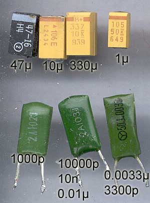
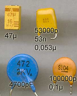
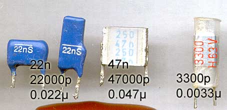
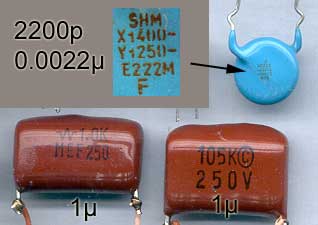
As passed one year after I bought it and there is no warranty I decided to get rid of annoying high pitch noise in audio channel. Also OSD graphics was a bit distorted. I though that it is some power supply problems. I opened the case and made very small modifications. Replaced 1000μF x 10V capacitor with 3300μF x 6.3V one on 5V power line. Also increased cap on 12V line. Also added small (47μ and 10μ tantalum caps on same power lines). Also, I have big collection of mountable feritte core beads. So I placed as many as I could on the power lines.

Vido DVD/DivX player

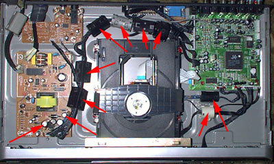
The noice on audio lines decreased about 50% and on screen display is quite good. Only one notice- 3300μF cap is getting warm. This means, that power supply is still overloaded. I thing this PSU is too weak for this device- 5V is 4.9V, 12V is 11V.

Posted in Anything | Leave a comment

Irwin Unibit drill

For drilling wide holes in thin sheet metal I bought Irwin Unibit drill bit. It is self-starting drill.

Irwin Unibit

For testing purposes I used steel sheet from ATX power supply box. Starting hole is a bit angular, next sizes are quite good. Only need to adjust the speed of the drill- to cut the steel, not grind.

Irwin Unibit

Posted in Anything | Leave a comment

Thermocontrolled Fan, ver 3

In previous circuit, the temperature turn on the fan instantly. The regulation period is very short. To make it more wide just add only one resistor (R5):

PWM Fan control circuit

While adjusting sensitivity of your schematics use potentiometer instead of R5. It must me about 100K … 1M range. After fine tuning, measure the resistance of potentiometer and replace with simple resistor with same nominal value.

Don’t forget to add capacitors near error inputs. Circuit is quite sensitive and various interferences can start the fan.

Posted in Anything | 1 Comment

Thermocontrolled Fan, ver 2

This small modification in the older schematics made it sensible to temperature.

Termofan 2

Main difference from older circuit is that I used one of error comparators for NTC thermoresistor. R3 and R4 must be equal or something near to make temperature adjustments easy. As at this moment I have only one potentiometer at hand so I removed fan speed control.

more…

Posted in Anything | 2 Comments

PWM Fan control

It is simplest PWM fan speed control circuit from scrap. The detail values are not very critical.

Here is the schematics:
PWM FAN control
R1-~10K, R2-~100K, C1- 0.01μF, chip- TL494, KA7500. It would be good practice to put some electrolytic capacitor between Vcc and GND near the chip.

Using potentiometer R2 you can adjust fan speed.

While PWM?
MAJOR PRO: Almost no heat is produced by the circuit – you can use it without a heatsink.
MAJOR CON: Since there’s no constant power for the circuitry in the fan, RPM sensing/failure detection will be erratic at best.

The schematics is simplified to the lowest level. So it may not work with some fans. On my testing breadboard it works with some fan from PSU (DC12V, 0.14A, brushless). The TL494 output power can be from 2x200mA to 2x500mA (depending on manufacturer). The fan current must be less than chip’s output current.

more …

Posted in Anything | 3 Comments

Values of the capacitors

In every schematic you can find few capacitors. Sometimes you remove old caps from some junk boards. And sometimes it is difficult to determine the cap value. There is some standards for cap coding, but not every manufacturer take care about it. The capacitance is measured in farads. But one farad is very big value, so people use fractional parts of it. These parts are decimal and called using old names:mili (m, *10-3), micro (μ, u, *10-6), nano (n, *10-9), piko (p, *10-12).

I have difficulties translating nanofarads to piko or microfarads. So I am using this picture. It helps me. Just imagine you cap value written on the picture and you can read the value in other form:
cap scale

Standard says, that there are only two digits on the capacitor body, the value is expressed in pikofarads (47 = 47pF), if numbers are three the first two number show value and last is representing multiplication value, or just how many zeros you must add (472 = 4700pF). But in real world …

Just look at the scans:

caps
In the first row you can see SMD tantalum caps. They never be in pikofarads 🙂 , so two digit caps is in microfarads. Sometimes manufacturer print Greek letter mju – μ, to show that it is microfarads. On the second row there is another curiosity- the value of small cap is printed in mikrofarads- .0033, the leading zero is omitted. I think is is old matsushita or victor company in Japan cap.

caps
Here is that tantalum with μ and other standard caps.

caps
And here is old “European”, I think Siemens made capacitors. The “n” shows that value are in nanofarads. On far right the cap is without letter- value is in pikofarads.

caps
On the top row is special capacitor for protection. One side is full of various certificates, while on other you can see very small print of value. On the bottom there is two identical caps made by different Chinese manufacturers.

And the best thing is, that always use multimeter to measure the value of the caps. Especially if you are playing with SMD ones.

Posted in Anything | Leave a comment

More tubes

As I wrote in other article, we received some old Japanese made old hardware. On Friday I opened some big device and removed few more lamps.
6as7
This was power supply. And one heavy used and another quite new 6AS7. Also 5AR4 and 12AX7. The power supply was repaired in circa 1984. And one 5AR4 was replaced with silicon diodes. Also removed some very nice and big inductors- 10H @ 100 and 250mA. Also very well made power transformers, but they were designed for operation in japan- 100V and 60Hz.

Posted in Anything | Leave a comment

NOS Vacuum tubes

Arrived big box for recycling and I found big stock of NOS (New Old Stock) radio vacuum tubes. It is the set for repairing some scientific devices. Now these tubes are used in cool hifi audio amplifiers. According to documents, the lamps arrived to USSR in 1977. Most of the lamps are manufactured in 1966. Made in Japan.

NOS tube stock

Here is the list of the lamps:
(model, manufacturer, quantity)

With boxes:
T66G, Toshiba, 10
12AX7, Matsushita, 30
6CA7, Matsushita, 6
12AF6, Ten, 6
6AL5, Toshiba, 19
12BH7, Toshiba, 10
GRA3, Toshiba, 4
5AR4, Matsushita, 9
6AN8, Matsushita, 9
VR150,, 4
5651,, 3
6N015, Apollo,5
CD25,Rodan,5
6V6GT,Toshiba,5
6BQ5, Matsushita,4
6V6,Ten,4
6DJ8,Matsushita,4
6AU6,Ten,5
12AU7,Ten,3
6X4,Ten,1
12AU6,Nec,2
12AT7,Nec,1
12AX7,Ten,4
6RA5,Nec,2
B-300G,Nec,1
ECF82,Tesla,2
12BH7A,Ten,9

Without boxes:
12AX7, Ten, 25
12AU7, Ten, 14
ECC83, Telefunken,1
Russian: 6N1P-E, 6N2P

Posted in Anything | Tagged , | 2 Comments

UTP lightning protection

We have small local network at home. As it is hobbyist LAN, the cables goes in various strange ways- on the trees, near power lines and etc. We are using FTP ant unshielded (!) UTP cable. In summer, we have few thunderstorms every year. And every year we have dead switches and LAN cards. One year, lightning even managed to burn mainboard in my computer.

Lets look ant the schematics of realtek based UTP switch:
UTP switch

And now look at the photos…
UTP switch

Look ant 75 ohm resistors…

UTP switch

And take a look to the color of shield near the damage. It is not the smut from the flame. It is color of over heated steel. This means that there was electrical arc between resistors and metal frame. The ports are dead, but the device’s other ports are working fine.
I think, that the unshielded cable was connected to these ports and after lightning stroke there was minimum 2..3kV overvoltage here. The blue 2kV capacitors are undamaged. It is not the direct hit! If it was direct hit of the lightning, there would be big black hole here. The overvoltage was from inductive interference from distant lightning.
Using used details from scrapped telecoms equipment I’ve made very simple protector. I am using it for more than year and there was few nice storms this summer. The switch was killed, but my computer’s LAN card is OK. In the next weblog message I’ll show the schematics. It is very simple and LAN is working at 100Mbit/s without any problem.

Schematics of the devices.

Posted in Anything | Leave a comment

New graphics for my computer

For some reason, I need more space on my windows desktop. Especially when I edit video, draw images or create and admin webpages. My computer, with integrated i915 graphics didn’t work with second PCI video card. So I was forced to buy PCIe (pci express) video card. My main criteria was silent cooler. So I bought the card with passive cooler and heat pipe. A heat pipe is a simple device that can quickly transfer heat from one point to another. They are often referred to as the “superconductors” of heat as they possess an extra ordinary heat transfer capacity & rate with almost no heat loss.

Heat Pipe
Radeon X700, 256MB, heat pipe, no fans.

It started with any problems, except that some metal “design element for lamers” is very near to other card. Also, after restart, windows swapped primary and secondary displays. But after some configuration tricks I have my new windows desktop:

Dual View
Dual monitors on my table

Posted in Anything | Leave a comment