The beauty of laser beam

Just small note about the beauty of laser beam image. Laser beam is coherent light- the waves of the light are synchronized. So all theoretical effects of light can be viewed with naked eye. Here is the image of interference- some light is delayed and when the phase of the wave is opposite, the light disappears. Or it is just cool image.

The beauty of laser beam

And here is the detail of the image above. It is a pity, that digital camera can’t catch the “holographic” shine of the object.

The beauty of laser beam

It is unfocused red laser beam. I used DVD laser and some lenses. As lenses are not centered, the image is mushroom shaped. The current into laser is only ~75mA. Total distance the beam had traveled is about 6 meters. (18 feet)

Posted in Anything | Leave a comment

Some jokes

This web log entry was written in Lithuanian language before new year. It was just a joke…

My nephew decided to build holographic super computer as his science project. (It a partly true). Here is small glance to the upcoming project- all information about this project is about 15 gigabytes in my hard disk. But later I decided to destroy all information about this project because I want to protect human race. Humans are too young for this technology…

powerful stuff

Author of this idea is Henkas. In this photo, the authors is fine-tuning the holographic display.

We even disassembled old computer homograph to get some needed components.

power-full stuff

Posted in Anything | Leave a comment

Windows CE

I have already wrote about terminal computer I have. I didn’t managed to start Windows CE on it. Maybe there were some problems in configuration or something. After some time I received more terminal computer and they booted Win CE without any problem. The only problem was in the hardware- blow up capacitors in the power supply. I changed them and everything is fine.

terminalai

Terminals booted Win CE and I can see standard blue windows desktop. And some requester about connecting to some server. And nothing more. I checked contents of CF card but all information is “crypted” inside few system files. Somewhere there is all settings and passwords stored, but where? The only solution is to “damage” system settings file to force system to “default settings”. I noticed, that if I move (and even place it back) “system.hv” file, windows CE (at least this version I have) will reset to default settings. Or maybe to some semi-default settings. After this file manipulations I see configuration wizard when I boot computer. Then I press “cancel”, go to “Start Menu”, “Settings” or “Control panel”. Find “System” icon, press “reset to factory default”. After this manipulation systems reboot to its “virgin” state. Now I can configure system as I want.

I found WinCE 4.2 and 5.0 (or maybe all CF card are already upgraded to version 5). This version of Windows CE have installed Internet Explorer 6.0 without Baltic encoding. Unicode is installed and new web pages with unicode charset (like this weblog) are displayed with proper symbols. But all older Lithuanian web pages with Baltic codeset displayed with mixed symbols.

This is nice and slow fanless internet computer. There are some other software in install like remote desktop clients, file viewers and mail software.

While playing with CF cards and files inside it is important not to touch BLDR file in root drawer.

Contents of my CD card:

2003.04.15  18:38            16.384 BLDR                  
2007.12.06  20:04    dir          BMP                   
2007.12.06  20:04    dir          Documents and Settings
2020.01.28  04:38            67.739 EBOOT.BIN             
2005.08.20  16:18        15.484.163 NK.BIN                
2005.08.20  16:15           308.316 SPLASH.BIN            

Contents of Documents and Settings:

2007.12.06  20:04    DIR          default
2001.05.31  12:24                52 default.mky
2001.05.31  12:41           131.072 system.hv
2004.09.08  09:45                52 System.mky

Contents of default:

2001.05.31  12:41           131.072 user.hv

BLDR is the “second” boot loader. First one is in the first sectors of the disk. Splash.bin is startup (boot) screen image. It is uncompressed raw image. eboot.bin- unknown. nk.bin- is the image of windows ce operating system.

Posted in Anything | Leave a comment

Clearing-up the house

From time to time I am doing house clear-up. If I didn’t this, the house will be full of various electronic stuff. Some of the items maybe sold in eBay or local garage-sale, but some items must be thrown away.

Some stuff appears in the house in very simple way- I need some small part on the PCB, so I pick up whole PCB. And the rest of the board is left in the shelf- maybe I’ll use other components in the future. But not now IS THE TIME and everything must go away.

Electronics trash

In the picture there is green PCB with big BGA chip, near two gamepad joysticks. This PCB was picked up only for FM75 chip- tiny element with eight pins. I also removed some linear regulators from this PCB: 1.8V and 3.3V. They were used for FPGA breadboard. All other chips like big LG cpu, 28LV320AT flash, LV logic chips, LEDs, 100MHz oscillator and lots of SMD components are trash.

Here is bigger picture of the trash to exam.

Here is the list of the trash: Logitech web cam (old one, slow, low res and low sensitivity. Replaced with new no-name), VFD screen with drivers from DVD, TI DSP board, few gamepads (I removed radio modules), CB radio with broken display panel, computer mainboard, old IBM notebook (I removed only few chip from it), some optical mouses (I was searching for specific chips), one wireless mouse, bunch of small motors (gamepad vibrators), some unidentified PCB, some old DIMM and SIMM modules, old HP 5300 scanner (replaced with new-old HP6300 with better lamps). This is my fourth scanner- and only first one (HP5p) was bought in the shop. All others were picked from the trash. These old scanners are much better than new cheap ones .

All this stuff is found in my room. And if we’ll look in to the garage…

Posted in Anything | Leave a comment

Laser power supply 2 adjustments

Warning! Laser
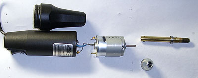
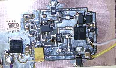
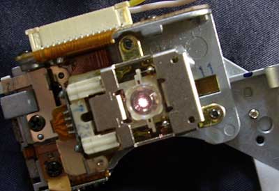
As I mentioned, laser diodes are fragile devices. So the power supply must be adjusted before connecting any laser diode.

After all components are placed on PCB and visual inspection is finished, connect one 1.2K resistor in R4, R5 and R6 place. Power up the circuit. Check if linear regulator is working and we have stable 5V in the 7805 output. Measure voltage in the empty laser diode place. It must be less than 5V. Connect ampermeter instead of laser diode. Ampermeter must handle 1A current. In one position of the trimmer, the current in zero, in other some value. Set max current value by adding additional resistors in R4, R5 and R6 place. It is not very important to use exact resistor values in this circuit. Something in similar range is usable. I place 13K in R7 and everything is fine. Graduate trimmer to output current values.
Connect in series to ampermeter any powerful diode (I used optically burned laser) and check the current. It must be same as before and trimmer scale must be same.

This device must be powered to power source capable to output ~1A current at ~7V. If input voltage is higher (I use 12V Pb battery) the 7805 gets hot at max power. Use any heat sink to keep devices in working temperature.

Usage:

Connect (solder) laser diodes only to switched off and disconnected device. I repeat- DISCONNECTED. I damaged few laser diodes due to ground loop effect. The voltage between switched off laser power supply and ground soldering iron was high enough to damage laser diode.

Set current to min, switch power supply. Increase current. At first, laser diode is only glow. It is simple LED emitting effects. Optically burn out laser diodes can emit LED light. Increase the current and in some moment, laser diode start to shine very bright- it means that laser generation started. Now you can increase the current up to mentioned in datasheet. Or just try to find max current by your self. High current kills diode, so be careful. Especially when testing burning and ignition experiments*.

IR laser from CDRW device is powerful too. It can withstand 200…300mA current, but “working” current is about 100mA. IR laser beam is invisible and if you use digital camera to watch IR light, be careful. You can burn out not only your eyes, but digital sensor too. 🙂

Do not forget to use heat sink on lasers. In max power mode even quite big heat sink become hot.

Also, don’t forget laser safety… (image from www.electricstuff.co.uk – BTW nice web page)
Big Scary Laser

*more experiment will be translated in near future. Take a peek to Lithuanian blog.

Posted in Anything | Leave a comment

Laser power supply 2

I’ve made some improvements to my laser PSU. I added voltage regulator, max voltage on open laser suppressor, spike suppressor. Also some useless improvements…

laser psu schematics 2

I didn’t made new PCB, I tested modifications on old board. But all modifications I entered into Eagle software and traced PCB.
I think this “theoretical” PCB is good.

PCB of laser PSU 2

Main difference from old version: IC2- 5V voltage regulator, C4 capacitor, R11 resistor. Capacitor C2 must be very small. It is used to prevent high frequency oscillations. If the capacity is too big, it will shunt input of amplifier and the inrush current through the laser will be very big. PIN2 theoretically is connected to photo-diode build in laser. But all new high power lasers don’t have photo diodes. So this pin typically is left unconnected. So, the resistor value is unknown. D1…D3 are fast schottky diodes. They prevent from reverse voltage during various experiments and connections. One of them is useless. 🙂

Laser diode body is connected to regulated supply, so take care that heat sink and laser body is not connected to ground plane. If it is connected, your laser is dead. It is possible to build PSU with grounded body, but I don’t have p-channel power mosfet in my stock. Laser diodes are static sensitive devices- handling precautions required. I damaged few diodes by simple ground loop- my solder iron is grounded and laser was powered from some wall adapter. Ground loop killed diode. Disconnect laser PSU from main while connecting/soldering laser diode.

Use the link and make your own PCB using UV of hot-iron and laser printer method.

PCB image (600dpi).

Here is experimental board (version 1 with modifications):

Laser PSU experiments

Posted in Anything | Leave a comment

IR vs Red

Warning! LaserI improved my laser PSU design: added voltage regulator, additional schottky diodes, some capacitors and it seams that laser supply is quite stable. I tested it with low power led lasers and several high power IR lasers from CDRW devices. Heat sink on the PCB is not mandatory. Only in rare cases, when powered from 12V and using extra power to diode, PCB is hot. As I changed some resistors, the current range is smaller. I decided, that I will not try to pump extra power from these small lasers. Now the range is from 0 to 200mA.

IR vs RED

There is two lenses in the photo near PSU. I removed these lenses from photocopier. One lens have build in IR filter, other lens is made from clear optical glass. The bluish color of filtering lens is from copper ions in the glass.

And now, small experiment about wavelength filtering. Take note, that IR laser is much more powerful than RED. Red laser in this experiment is from cheap DVD player.

IR vs RED

As we can see, special lenses filter IR light quite efficiently. Similar IR filters are placed inside all digital cameras. Sometimes it is possible to remove this IR filter and get very weird IR camera. The problem in modern USB web cams is, that IR filter is build in camera’s lenses and it is impossible to remove it. The RED beam cross both glass lenses without any visible problem. (Color change of the photo is due to white balance- digital camera set bluish color as white base).
The current through the diodes in both case was about 40mA (IR laser is in low power mode, for “reading”).

Small movie: IR laser. 100mA. From CDRW. Unfocused. (xvid, 1.5Mb)

Posted in Anything | 2 Comments

IR laser

Warning! LaserMy red laser stock was empty. Mainly due to my errors and experiments. As I didn’t find spare DVD recorders, I switched to infrared lasers (IR). It is much easier to find powerful IR laser- the source is any CDROM recorder. In newer high speed CDRW devices, lasers are quite powerful.

IR laser beam is invisible. Sometimes you can see so red light emitting from laser diode (do not stare to focused beam). It is not a miracle- you can’t see these wavelengths. It is just secondary LED emission near the cavity of the laser. Even if the laser part of the device is burn out, you can see this reddish light. Laser emission is very interesting phenomena- when we increase the current through the diode, we get LED light. As we increase current, suddenly optical generation starts – laser process is on. All low power and old lasers have photo-diode to detect this process and to measure optical power. New high power laser modules do not have photo-diodes installed, even the laser is in 3 pin package. You can notice, that third pin is not soldered to PCB. And if you disassemble laser itself, you can see, that there is not wire connected to this pin. Neither you can find photo diode. I wanted to get modern driver chip datasheets from elentec-intersil, but I received answer, that these documents are not for wide publication. Why? I don’t know. These chips are in every modern DVDRW device… So I can’t find how laser power is regulated in these devices.

I improved my power supply and started tests with lasers. Did I mentioned not to power high power laser diodes without coolers? So don’t.

To detect IR beam use any digital camera, USB camera or any other consumer device with CCD camera. CCD cameras’ have IR filter, but it is to weak to block laser beam.

IR laser

This nice photo is made when I placed my digital camera lens to CDR recorder optics. As optics is untouched, we can see nice interference pattern. Just cool photo.

IR laser

Posted in Anything | Leave a comment

Laser Power supply

This is first version of laser diode power supply. I borrowed circuit from die4laser.com and changed it a bit. It is classic current source using n-channel power device. It is better to use p-channel devices here, but now I have only n-channel mosfets on my workbench. They are cheap and easy to get. Modern mosfets a very compact and powerful devices. Now they are very steady devices and even can work in very high temperature. During experiments I overloaded supply and transistor self-melted solder (I am using lead solder)- working temperature of particular device is 150oC!

laser diode power supply circuit diagram

Resistors R4, 5, 6- they are used to set max current. R8- is shunt. If we place here 1 ohm resistor, we get 1V reading for every ampere. R2, 9 -1k. R1 is about 600 ohms. R3, C1- is soft start circuit. Not implemented in current design. C2- only few hundreds of picofarads. Only to prevent from auto-generation. C3- is a bigger one. Transistor- any n-channel mosfet powerful enough to carry working currents and voltages.

PCB graphics of laser diode power supply

This is PCB image. If this picture is printed with 200dpi resolution, it can be used to build PCB.

This WAS prototype of power supply. It killed few laser diodes. So I made another version and I place circuit diagram in next blog entry when I’ll translate it from Lithuanian version. I recommend to use regulated power supply and not more than 5V.

Posted in Anything | Leave a comment

DVD laser

Warning! LaserThere are lots of rumours in the internet about high power DVD lasers and about hacking them. I decided to test some of the rumours. Theoretically, there are two lasers in modern DVD recording device. Power of the laser must be strong enough to change the physical properties of recordable media. In this post, I didn’t examine IR (infra red) laser used in same device for CD/CDRW media. I tested RED laser used in DVD recording and reading. The newer DVDRW device, the faster recording speed- the more power in laser.

Laser diodes is CD/DVD drive come with various optical lenses. These optics is not very useful for burning experiments- the laser beam is separated and then focused in very short beam. And for real “laser gun” we need long range optics. There two types of laser diode modules- stand alone lasers and lasers with multiple photo-diodes (detectors) in same package. Older laser diodes were built with photo diode build in package. This diode is used to detect laser generation and to measure optical power. In some new devices this diode is missing. Even if the package have three pins, I didn’t find photo diode inside, even when I disassembled diode.

DVD laser

Laser diodes are sensitive devices. Especially they are sensitive to static discharges and over voltage-over current modes. I damaged 4 diodes experimenting with my power supply- the transitive process during power-up and power-down killed them. On some laser diodes there is optical element glued to package. It is beam splitter- you can get remarkable interference lines when using these splitters, but for power experiments we need to remove it. After removing, the “can” is open to free air (and some diodes are made without protection), so keep “open” diodes dry.

Laser diodes, same as LED diode is current, not voltage user. But using simple ballast resistor is not good way to solve the problem. The PSU for laser diode is current regulator with dual feedback: one from current, another from photo diode. And PSU with over voltage protection. The PSU is very simple (I’ll post two version of PSU I build). The components are very cheap and everything can be found in old computer motherboard.

DVD laser

Here is the image of working DVD recording laser diode without collimator optics. Other, simple diode without heat sing is seen too. Never use high power laser diodes without heat-sink. The current in threw this diode is about 150mA and according to the datasheet, the optical power is about 100mW.

If I place diode to my digital camera lenses I see such nice image. The light is dissipated, so there is no possible damage to camera detector.

DVD laser

Here is first experiments trying to focus laser beam. I used optical collimator some some old IR laser. This collimator is not very suitable to high power RED lasers. There is big problem to get good collimator for such laser.

DVD laser

And now some words about safety. Lasers used in DVD-R device and working in full power are potentially dangerous devices. So: NEVER STARE TO LASER BEAM WITH REMAINING EYE! IR (infrared) laser are double dangerous- they are powerful and invisible.

I found datasheet for Rohm laser diode RLD65PZB5: max optical power (pulsed, 50% duty cycle) is 240mW! Current according datasheet is about 400mA.

Posted in Anything | 2 Comments