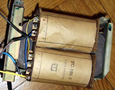
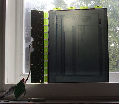
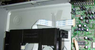
I need some transformer for one experiment (I’ll post it in near future). So I dig my trash pile and found Soviet transformer with double windings. The idea was to run the transformer with double overload. The transformer I selected was TC-180-2 from old tube tv set (in real, if you find cool Russian device, try to run web search using original Cyrillic. Even if the English version look same. So, check the ТС-180-2. This is different to TC-180-2 🙂 . Here is the photo:
Then writing TC means “power transformer”, in Russian-трансформатор сетевой. Next numbers is the nominal power in Wats. Nominal power, not some RMS or other Chinese or western invention. Nominal power means that I can get such power for unlimited time without any damage to the device. So I can get 180W of pure power from it. In bigger TV set I’ve seen even 270W transformers. Such 270W transformers are bigger than in my Maranz audio amplifier. And Maranz is rated 6x80W (480W!)…
These transformers gets to many hobbyist hands with removed connection wires. It is great luck, that mine transformer was with the sticker. But this sticker have some caveats.
It is written: 1-2-3, 1`-2`-3` = 127V/220V, 1.51/0.87A. But this text is quite uninformative. The real description of primary winding must be something like this:
1-2-3 means 0-110V-127V on one coil. On the second coild something similar: 1`-2`-3` means 0-110V-127V.
It is symmetrical coils. Now the simple arithmetic’s come to the first place: between 2 and 3 pin there is 17V.
If we have mains output 220V (old Soviet standard), we need to connect 2x110V. The connection is made in such way: mains cord is connected to 1 and 1`. The jumper wire is placed between 2 and `2. Now we have EU and more wide standard: the average voltage is 230V. (Also, this transformer is a bit overloaded, so we need to use more windings to improve the efficiency of the device). So we can place jumper between 2 and `3 or even 3 and `3. So we get 237 and 254V primary.
Secondary winding are made in similar way. The only difference, that the sticker now is correct:
5-6 is 59.5V/0.5A
7-8 is 43.5V/0.38A
9-10 is 6.4V/4.7A
11-12 is 6.4V/1.5A.
The out voltage is calculated holding in mind the circumstance, that input voltage is standard. As transformer is linear device- if we put a bit more volts in the input, in the out we get more too.
For my experiment I needed higher voltage. So I connected transformer in auto-transformer schematics.
Input 1 and 1`. Jumpers placed 2 and 2`, 6 and 6`, 5 connected to 1`. So I get: 220+59.5+59.5=339V. The output is connected to 1 and 5`.
In real world the output is a bit more, as mine mains voltage is 235V. This all stuff will be connected to variable auto-transformer and I’ll receive output from 0 to 400V.
Few warnings: out voltages are lethal. Auto-transformer connection is dangerous as even is device output few volts, the output pins can be at the high potential regarding ground. Before connecting untested transformer, measure isolation between primary and secondary windings and transformer core. As measure of the windings resistance didn’t show internal short circuit connections between same core windings, measure idle current of the transformer. It must be low. This particular transformer is overloaded from manufacturer, so idle current is about 150mA. It is high current for such power transformer. If we connect primary in “light mode”, the idle current is about 50mA. I recommend to use isolating transformer in your experiments and ground trip current relays. Don’t forget to ground the chassis of your devices.


