There are lots of China made LED board with HUB08 connector. Boards typically are single or two color ones, without variable brightness. Boards can be connected in daisy chain mode using 16 pin connector. There are specialized MCU boards from China with very ugly, sometimes password protected software. For custom use there are some bad coded Arduino “libraries”, but there is no protocol description. We will try to fill this gap and analyze China made controller and will connect some boards to STM32F103 “Blue pill” board.
The connector is standard 0.1″, 16 pin connector:
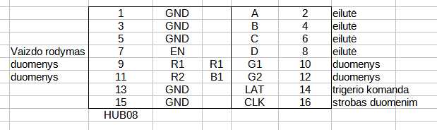
7 – EN, enable image; 9,10,11,12 – data input; 14 -latch (transfer data from SPI register to output register; 16 – SPI clock; 2,4,6,8 – select current line to show, total 16 lines.
General timing of the interface:
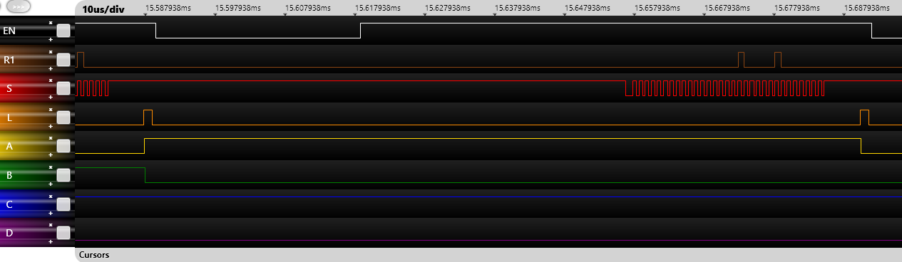
SPI clock was about 1.2MHz, horizontal line refresh ~11kHz.
How it works: transfer via SPI some pixel data (up to 4 channels), send short LATCH command (74HC595) to transfer data and for some time enable EN to show line. The LED boad has hardware protection for stalled data transfer. If static data are detected, the output is disabled. To keep image on the board the clocks must be active.
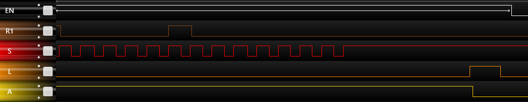
Clock timings details.
There are two ways to create image on the LED matrix board: dynamic creation of the image and transfer from video RAM. First method saves lots of RAM, but there must be very strict timing, like in Atari 2600. Second method is much easier, but we need video RAM.
For our experiment I decided to use video RAM method. I connected two boards in 64×64 pixel (LED) configuration.
As “Blue pill” board’s MCU has only one channel SPI (STM32F103c8t6) I made some strange connections on the LED boards- all SPI data lines are connected in series: Data from the MCU goes to R2 of the first board, R2 output from first board returns to R1 of same, first board. Output R1 of first board goes to R2 input of second board. R2 output returns to R1 input. Now we have 4 rows of 64 LEDs int the single logical row. We need transfer the data for 4×64 LEDs (bits), total 32 bytes of data. And repeat this for 16 lines. Total we need 512 bytes of the video RAM.
All Hub08 interface is interrupt driven: first we use timer interrupt for line start (Horizontal sync). In this interrupt we calculate video RAM addres and transfer 32 byte via SPI using HAL routines (somehow DMA SPI is not working! Maybe some error or fake chip on this PCB). How we wait for SPI finish interrupt. Here we select LED row, enable output, change some variables for the software interrupts and return control to the main program.
All software and source code:
Hub08 LED board interface with STM32F103 Blue pill source code and compiled HEX file.
Hub08 software have only the basic functions: plot and point (setting the point and reading color of the point from video RAM).