
There is a cheap, made in China product called “capacitive soil moisture sensor”. Some black PCB with few components and no coating:
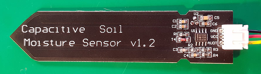
There are lots of “duino” projects for this sensor. But there are lots of comments about this sensor not working or working strangely and erratically. For my future project I need such a sensor, so I bought one to analyze.
Circuit diagram (schematics) for this “device” is something like this:
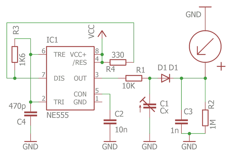
It is a bit simplified schematics, but I think it is more real compared to internet ones.
The 555 timer is generating high frequency voltage (1.7MHz) to the sensor plate “capacitor” via R1 limiting resistor. This resistor and “moisture” capacitor C1(Cx) is AC voltage divider. Resulting voltage is rectified with diode D1 and smoothered with a C3 capacitor and loaded with a very high resistance R2 resistor (sometimes missing). Resulting DC voltage (with extreme low current) is directly fed to the ADC of the MCU. This is the first error- not all MCU ADC input have such high impedance (resistance), also some parasitic voltages may be present on ADC pin with such high resistance. Also, any contamination of the PCB will drastically change ADC readings. We need to add voltage follower (op amp) to keep impedance high and stable. Also, isolation of PCB is important. Not only in the ADC part, but also on 555 timer to keep it running stable.This sensor (at least mine) does not work from a 3V power source. Maybe there is a very fake 555 timer. Need to investigate it more.
Possible improvements:
1. isolating coating with varnish. Maybe even some epoxy or UV curing one.
2. Remake of AC source. Maybe some crystal oscillator here? Or use something from nearby MCU.
3. Add voltage follower for impedance matching.or… use completely other hardware. something like an advanced capacitive touch controller like MPR121.
The MPR121 uses a constant DC current capacitance sensing scheme. It can measure capacitances ranging from 10 pF to over 2000 pF with a resolution up to 0.01 pF. The device does this by varying the amount of charge current and charge time applied to the sensing inputs.
Hi,
Thank you for sharing your investigation of this sensor. I also had problems with this sensor running at 3V. I removed the (fake?) NE555 and replaced it with a TLC 555. Now the board runs fine, even at 2.5V. My only concern now is that the board consumes too much power: the board takes more than 5 mA. Do you maybe have a tip on how to make this board work with less power?
BTW, the board has a U2 component (zero ohm resistor?) that is missing from your schematic.