
I have gathered graphic LCD monitors from old devices (mostly from copiers). That’s simple monochromatic LCD monitors without controllers. An image should be dynamically tranferred from controller for these monitors. There are SED1351 or similar graphic controllers mostly. Maybe it’s possible to find a datasheet of SED, but not to find the monitors. I’ll try to look into several LCD monitors with the help of an active board.
By the way, these monitors often need negative voltage supply. The main logic is powered from 5V.
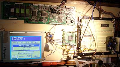
LCD monitor named “EDMMPU3BDF”, the white blue monochromatic graphic monitor 320×240, mostly has a touch screen.
1. screen_on (0-off, 5V- on)
2. nc
3. VSync
4. HSync
5. pixel clock
6. Vcc, +5V
7. GND
8. Vee, -25V (the same as pin 13)
9. D3
10. D2
11. D1
12. D0
13. Vee, -25V
14. contrast, ~-18V
Standard protocol is shown graphically (oscillogram):
Big picture for printing.
WF signal is used in several LCD circuits to generate the alternating current through LCD crystals in order to protect metallization from erosion. Not all LCD monitors use this signal. There is simple logic signal, which changes to each picture.
Hi there,
I just bought one o this LCD’s and im trying to write something on it using a pic microcontroller. I’ve seen in your picture above that you already controlled one. Or is it connected to the original board from the copier?
Can you please tell me the timing of the signals presented in the picture above? Frequency of Vsync and Hsync (how many milieconds for ON and OFF)
Hi sethmad, this blog is only very slow translation of Lithuanian blog. My friend, Orinta ir doing this job and at this moment she is lazy bone. 🙂
Yes, the picture above is with original controller.
You can not use simple MCU to control this LCD as this LCD do not have video RAM. You need to refresh all screen at least 20… 30 times per second or it will flicker badly.
All these LCD are controlled on same manner. Here is some links to my lithuanian blog:
http://www.vabolis.lt/2009/04/03/dar-vienas-grafinis-lcd/ -small LCD from old handheld computer.
http://www.vabolis.lt/2009/05/10/kameros-sensorius-tiesiogiai-i-lcd-ekrann/ – direct data transfer from camera sensor to this LCD
http://www.vabolis.lt/2007/05/13/lcd-fpga/ – bigger LCD
http://www.vabolis.lt/stuff/20070619.gif -how it was organised in simple logic.
I even managed to drive some LCD from LPT port. But it was tooo slow (few fpd). I’ve done this to analyse protocol.
http://www.vabolis.lt/2007/03/17/didelis-lcd-be-kontrolerio-prie-printerio-port/
I think in most case there is source code published in my web. Sometimes in the comments.
Now about the timing… Whole screen must be refreshed about 50 times per second. Some LCD reccomends 80fps. This is base number. Now you can divide this by total pixel count adding about 10 pixels to width and about 3 lines to height. It will give you pixel clock. And everything is calculated using this pixel clock.
Thanks for the fast reply 🙂
Looks like more complicated than I thought. but when I’ll buy an FPGA development kit, i’ll try this.
During my long google searches i’ve found this:
http://www.lcdinfo.com/products/usb13700.html
Looks like and USB interface to control this LCD’s. But It’s expensive.
i’ve a yamaha musical synthesizer psr-2100 with it’s lcd EDMMPU3BCF (without touch,14pins, stn type). Can i replace my display with this edmmpu3bdf ? Please inform me as soon as possible…
This blog entry is more than 3 years old. I do not even have a clue if these screen are interchangable. The only thing is just test. ALL the screens of this type are simmilar, the difference in minimal and typically in connector type, physical dimmensions…
HI
In pin description is a small error – numeration of pins are reversed. Pin Contrast is marked 1 on LCD pcb. I burn one display but I have another from old copy machine 😉
pin numbering depends on manufacturer. Sometimes even LED backlight is placed in other side and numbering is another.