I’ve made some improvements to my laser PSU. I added voltage regulator, max voltage on open laser suppressor, spike suppressor. Also some useless improvements…
I didn’t made new PCB, I tested modifications on old board. But all modifications I entered into Eagle software and traced PCB.
I think this “theoretical” PCB is good.
Main difference from old version: IC2- 5V voltage regulator, C4 capacitor, R11 resistor. Capacitor C2 must be very small. It is used to prevent high frequency oscillations. If the capacity is too big, it will shunt input of amplifier and the inrush current through the laser will be very big. PIN2 theoretically is connected to photo-diode build in laser. But all new high power lasers don’t have photo diodes. So this pin typically is left unconnected. So, the resistor value is unknown. D1…D3 are fast schottky diodes. They prevent from reverse voltage during various experiments and connections. One of them is useless. 🙂
Laser diode body is connected to regulated supply, so take care that heat sink and laser body is not connected to ground plane. If it is connected, your laser is dead. It is possible to build PSU with grounded body, but I don’t have p-channel power mosfet in my stock. Laser diodes are static sensitive devices- handling precautions required. I damaged few diodes by simple ground loop- my solder iron is grounded and laser was powered from some wall adapter. Ground loop killed diode. Disconnect laser PSU from main while connecting/soldering laser diode.
Use the link and make your own PCB using UV of hot-iron and laser printer method.
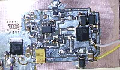
Here is experimental board (version 1 with modifications):