I installed video surveillance system at my work place. Nothing special 6 color CCTV cameras, one computer with few hundreds of gigs storing about a month of h.264 video. But I had a problem with one camera. The distance from camera to computer is not very big, about 300 meters (~900 feet). But the problem was that cable must pass several storage and manufacture workshops. With very electrically noisy environment. Also, the ground potential in the ends of cable is different. So, I decided to use already installed UTP cables. There are lots of commercial solutions to transport video over UTP cable. But my budget was very small, in fact I managed to empty it before this UTP problems… 🙂 I bought cheap, passive BNC to UTP video balloons. Connected… and it was great disappointment. Mine video baluns didn’t have galvanic isolation between UTP and coaxial cable. Also, the signal strength was very low and full of noise. This was my mistake- in fact, video balun is not simple 75 ohm to 100 ohm line transformer, but some auto-transformer. And the transformer rate is 1:1. don’t believe to all mystical distances adverted in balun description…
There were some problems to solve:
1. Galvanic isolation- to remove ground loop effect.
2. Convert asymmetrical coaxial cable to symmetrical and vice versa in wide frequency band. (50Hz…5MHz).
3. Cancel all possible interference from working devices in workshop.
4. Compensate loses in UTP cable.
The only solution is active amplifier. I selected old chip from Elantec (now Intersil) EL2044C (Low power, Low voltage, 120MHz Unity-Gain stable operational amplifier) from some video multiplexer. This chip is intended to use in video device, wide supply range (from 2.5V to 36V), output designed for 75 ohm video load.
Most complicated part in this design is transformer. It must be very wide frequency range. In transmitter side I used passive solution- I used that video balun. It will convert to symmetrical signal video output from camera without any additional devices. On the receiver size I build small box with PSU and video amplifier. May problem is transformer specifications- all internet is full of “buy it” solutions and no “make yourself”. I don’t know how many windings must be in the transformer and what size or core to use. So I decided to use “connect and test” version. Using spare UTP cable I connected “line emulator”. I had about 120 meters of cable, so I connected all pairs in serial to get 4×120, about half of kilometer of signal cable. Video source- DVD player. On other side TV. First transformer I selected made bad results- it was possible sometimes to catch video, but now colors and lot’s of other problems like shades. I connected oscilloscope to the end of cable and revealed, that there are lots of reflections in cable and high frequency part of signal is lost in transformer. Color in PAL is transferred using 4.43MHz frequency and all this color component is very low. I added some capacitors to increase gain in higher frequency, but this didn’t solve the problem.
Suddenly, while browsing the internet, I found some web-page about one man using transformer from old LAN card to transmit 10MHz signal over symmetrical cable. I grabbed old LAN card and used transformer… The “color” situation was better, but I’ve lost low frequency part of the signal… The final solution was a bit crazy: dual transformer. One for high frequency and other for low. Both transformers connected in serial. Don’t mix phases in transformer.
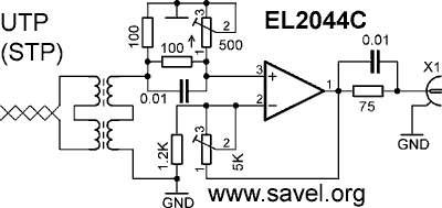
Final circuit diagram (schematics) of the amplifier:

Upper transformer is from LAN card. Lowe one is some from some power supply- it was feedback transformer on ferrite ring.
I don’t remember real value of the capacitors. 100 ohm resistor near transformer is main line load. Capacitor is used to increase high frequency gain. 500 ohm trimmer is used to adjust the reflections in the cable. Horizontal 100 ohm resistor is less that 100 ohm. I don’t remember (about 47Ω). Transformers are 1:1.
5 kΩ trimmer is to adjust gain.
PSU is double voltage, +6V and -6V, made from 12V with synthetic ground.

Winding your own impedance matching transformer shouldn’t be too hard. Rip open one of those impedance matching baulins and remove the binocular core. Clean out the wiring in the core. Take some thin gauge enameled wire and start winding. I’m sure you’re not using high powered stuff, so something simple should work. Here’s a website about building power splitters for ham radio stuff: http://www.dxing.info/equipment/rolling_your_own_bryant.dx
This is some Japanese guy who does ham. This link has more info about winding: http://www.intio.or.jp/jf10zl/fb801.htm
At low power (below saturation), ferrite core transformers have really good bandwith when properly terminated. Even if you only get close to the frequency response you need, “tweaking” or “peaking” with variable capacitors should give you a good flat response.