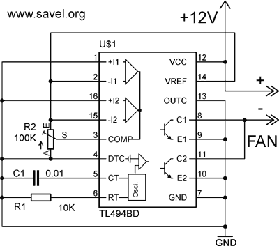
It is simplest PWM fan speed control circuit from scrap. The detail values are not very critical.
Here is the schematics:

R1-~10K, R2-~100K, C1- 0.01μF, chip- TL494, KA7500. It would be good practice to put some electrolytic capacitor between Vcc and GND near the chip.
Using potentiometer R2 you can adjust fan speed.
While PWM?
MAJOR PRO: Almost no heat is produced by the circuit – you can use it without a heatsink.
MAJOR CON: Since there’s no constant power for the circuitry in the fan, RPM sensing/failure detection will be erratic at best.
The schematics is simplified to the lowest level. So it may not work with some fans. On my testing breadboard it works with some fan from PSU (DC12V, 0.14A, brushless). The TL494 output power can be from 2x200mA to 2x500mA (depending on manufacturer). The fan current must be less than chip’s output current.

Pingback: Savel brain dump in English! » Blog Archive » Thermocontroled fan
Pingback: Savel brain dump in English! » Blog Archive » Thermocontrolled Fan, ver 2
Hi, isn’t the parallel configuration (pin 13 low) going to give you a limited duty cycle of only up to 50%?
Connecting pin 13 to pin 14 (Vref), with no other changes, would give full duty cycle range at half the current capacity.
Most 12V fans take less than 200mA, so that would still be within specs.