
Now let’s make some high voltage! As the schematics is done on the breadboard, I can’t produce high power application. This is because of very long wires used in the experiment. Also there is no any heat sink on the power mosfets. Connect transformer to the output stage according this schematics:
Push-pull load
The primary windings of the transformer are identical windings with about 10 turns. The secondary winding is about 100. So the transforming ration is 1:10. If you put 10V to primary, you must get about 100V in the output. The core is made from ferrite. I used some middle sized core from PC ATX power supply.
Be careful, the output on the transformer in under high voltage. The current is very low and will not kill you. But you’ll get nice zapp. One more danger- if you place big capacitor on the output, it can store fatal energy value.
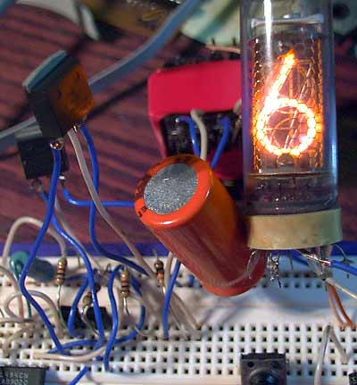
Nixie on the output.
Nixies are working from DC voltage. This nixie needed about 160V to start. (The power supply of the device is about 15V- small wall “cube”)
(Other parts used in schematics: PHB55N03LT, 500 and 1K resistors, IN539 diode, unknown value HV capacitor, ИÐ-14 nixie, C1685 transistors from old Panasonic TV, 1000mkf capacitor)
Pingback: Savel brain dump in English! » Blog Archive » TL494 - magic chip, Part 3
Pingback: Savel brain dump in English! » Blog Archive » TL494 - magic chip, Part 5
Pingback: Savel brain dump » Blog Archive » TL494 - universali mikroschema, 6 dalis