
I found the information about optical mouse hacking on the Internet (http://spritesmods.com/?art=mouseeye). I had been looking for such mouse for a long time. The first which I found, had defective optical chip. But the second was more succsessful.
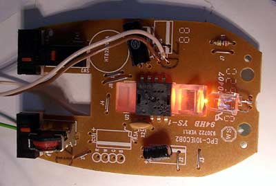
You need to find an optical mouse of the older model, where the optical chip has 8 legs. A mouse of the new model has only one chip, where all interfaces (USB or PS/2) have already been integrated into the same chip.
The program was not written by me. However everything is quite clear. All data – change of coordinates and even the view under the mouse pad are read out through 2 wires. Here is an image got “through mouse eyes”:
Here is a scanner mode:
A connection scheme is very simple – the mouse is powered from 5V. Connect SDIO pin and LED’s anode (+) to the 12th leg of printer port, LED’s katode (-) – to the 5th leg and SCK – to the 9th leg. You need to check if mica and LED (mouse elements) are connected. Then disconnect SCK and SDIO pins coming into mouse controller. The collocation of optical chip (ADNS-2610, A1610 or like) is following: 1 and 2 – mica, 3-SDIO, 1-SCK, 5-LED controll, 6-GND, 7-Vcc(+5V), 8-RefA (here a small capacitor is connected).
The software is the same as in original post. As my LPT1 port has burned out, I added additional I/O addresses of PCI board.
You can download source code and compiled MS Visual Basic program. There is one dll file (inpout32.dll) which you should copy to windows/system32 folder.
I am using ADNS 1610 in windows with given code.I have done all the things you described.I cheacked the mouse it works well.So why wont it give me output.Do i need to cut down SCLK & SDIO traces in PCB and how faster it scan the text.If you have the datashit of it please mail me robel.sharma@gmail.com
Do you have clock output from computer? Take a note, that my printer port on mainboard is dead. So I am using add-on card with base address &hBC00. This is not standard.
Yes, you need to cut data and clock traces from MCU to sensor.
Do i need different clk input. I am using printer pin(PP) 9,5,12,25.
I wrote, that my printer port’s logical address is not standard. Select your printer port address, start the program and check if you have clock output on chip’s CLK pin.