
Very often I need regulated PSU when playing with breadboard. And I need negative power supply too. Especially when doing something with operational amplifiers or old LCD modules. Typically I use 78xx or 79xx regulators in my experiments. But last experiment was draining lots of power and 7805 was very hot. And I use wall adapters as my PSU. So if I need dual voltage, I need to use two adapters. Also, the regulators take too much place in the breadboard and are not very efficient. So I decided to build add-on for my breadboard.
Here is the result:
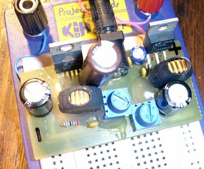
It is not a miracle 🙂 It just old, refurbished LT1076 chips from some old video multiplexer (I found nice dual port RAM and fast ADC/DAC too…). One LT1076 is working as standard step-down regulator and other as inverting. All outputs are regulated using simple variable resistors (blue ones on PCB). The output of positive regulator is from Vin to 0V. Negative output is more wide- when I was using small 7.5V, 1A wall adapter I managed to get output from 0 to -25V (with low load).
L1 -46uH (mine 100uH didn’t fit into PCB), R3- 3K. C1 and C3 any. R1 and R2 is one variable resistor, 10K.
L1 – 22uH, R1 and R2 ~20K and 40K. R3 and R4- one variable resistor, 10K.
To repeat this psu you can download Eagle schematics and board files.
The PCB is adapted to my breadboard, you may need to adjust the distance between output pins. All components are “through hole” except diodes- they are SMD. Also when I was populating the board, some capacitors were changed to SMD ones as “through hole” somehow didn’t fit.
Also I later added small heat-sink to both of chips using rubber isolators, as with some heavy loads the chips are getting warm.